In thermal testing, the accuracy and repeatability of your results depend heavily on the equipment you use. A high temperature chamber that fluctuates, drifts, or fails mid-test can compromise months of research and lead to costly product recalls. This article explains why investing in a reliable high temp chamber is not merely a convenience but a critical requirement for any serious thermal testing program. We will explore the risks of unreliable chambers, define the key attributes of reliability, and demonstrate how HEATEST Instrument addresses these challenges with precision engineering and robust design.

Why Reliability Matters in Thermal Testing

Thermal testing is performed to validate how materials, components, or assemblies behave under controlled temperature extremes. Whether you are testing electronics for automotive applications or aerospace composites, the chamber must maintain its set point within a narrow tolerance. A reliable high temp chamber ensures that every test cycle is reproducible—without unexpected temperature spikes or dips that could skew data.

Consider a scenario where a chamber drifts by just 2°C during a prolonged soak. For a material with a critical transition temperature near that range, the test results could indicate failure when the part is actually within specification—or worse, accept a flawed design. The financial and safety implications are enormous. Therefore, reliability directly translates to data integrity, product quality, and regulatory compliance.

The Cost of Unreliable Chambers

  • Test failure and rework: Inconsistent temperature control leads to failed tests, requiring additional cycles that waste time and resources.
  • Product liability risks: If a product passes testing due to a chamber error but fails in the field, your company faces recalls and reputation damage.
  • Maintenance downtime: Frequent breakdowns of low-quality chambers interrupt testing schedules and increase operational costs.

Key Indicators of a Reliable High Temp Chamber

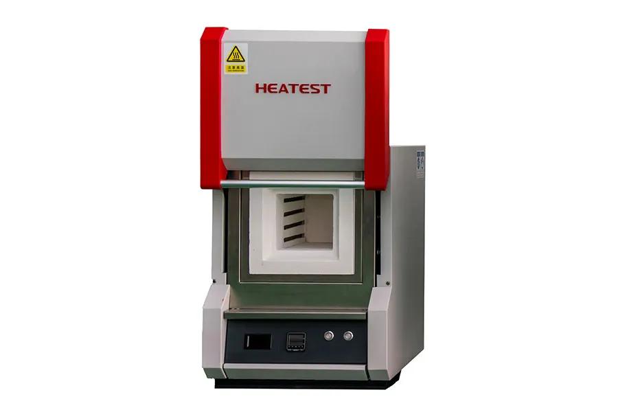
Refractoriness-test-furnace

Not all chambers labeled “high temperature” are built to the same standard. When evaluating options, consider these critical reliability factors:

Temperature Uniformity and Stability

A reliable chamber maintains uniform temperature across the entire workspace. Look for specifications that guarantee ±0.5°C uniformity at the set point. Stability—the ability to hold temperature without oscillation—should be within ±0.1°C. HEATEST Instrument chambers are engineered with advanced airflow systems and high-precision sensors to achieve these metrics consistently.

Robust Controller and Safety Features

The controller is the brain of the chamber. A reliable system uses a PID controller with self-tuning capabilities, redundant overtemperature protection, and real-time data logging. Safety features such as overheat limiters, door interlocks, and audible alarms prevent catastrophic failures that could damage both the chamber and the test samples.

For more detailed information on why your thermal testing requires a reliable high-temperature test chamber, please click here: https://www.lyheatest.com/tester-knowledge/high-temp-chamber-guide-1/

In industries where thermal performance determines product safety, reliability, and regulatory compliance, the accuracy of high temperature test equipment is non-negotiable. A deviation of even a few degrees can lead to flawed material characterization, rejected batches, or costly recalls. Yet many facilities operate with aging or poorly maintained systems, unaware of the drift that degrades their readings over time. This article examines what defines accuracy in high temperature testing, explores the factors that introduce error, and presents how HEATEST Instrument designs equipment that consistently delivers reliable, traceable results. Whether you are evaluating your current equipment or planning a purchase, understanding these principles will help you make an informed decision.

Why Accuracy Matters More Than You Think

High temperature testing spans applications from aerospace alloy development to automotive component validation and ceramic processing. In each case, the test data drives decisions—material selection, process optimization, quality assurance. If the equipment reading is off by 0.5% at 1200°C, the actual material behavior could be radically different from what the report shows.

The consequences of poor accuracy include:

  • Invalidated research results that waste time and resources
  • Undetected material weaknesses leading to field failures
  • Non-compliance with industry standards (ASTM, ISO, etc.)
  • Increased production costs from false rejections or rework

Accuracy is not just a specification on a datasheet; it is the foundation of trust in every measurement your lab produces.

Key Factors That Influence Temperature Measurement Precision

Visible-pore-density-tester

Accuracy in high temperature equipment depends on a chain of components and environmental conditions. Understanding these factors helps you identify potential weaknesses in your current setup.

Sensor Quality and Calibration

The thermocouple or resistance temperature detector (RTD) is the first link. Type S, R, or B thermocouples are common for high temperature ranges, but their purity, wire uniformity, and junction stability vary by manufacturer. Even a premium sensor drifts over time due to oxidation, thermal cycling, and contamination. Regular calibration against a traceable standard is essential. HEATEST Instrument uses NIST-traceable calibration protocols and recommends annual re-calibration to maintain certified accuracy.

To learn more about the accuracy of your high-temperature testing equipment, please click here: https://www.lyheatest.com/tester-knowledge/temperature-test-accuracy/

Selecting the right high temperature test chamber is a critical investment for any quality assurance or R&D laboratory. With dozens of models on the market, focusing on the wrong specifications can lead to inaccurate test results, compliance failures, or unnecessary operational costs. To help you make an informed decision, this article breaks down the five key specifications you must compare before purchasing a high temp test chamber. Understanding these parameters will not only ensure your chamber meets current testing needs but also provide scalability for future applications. Trusted manufacturers like HEATEST Instrument engineer their chambers with these precise requirements in mind.

1. Temperature Range and Uniformity

The most fundamental specification is the temperature range the chamber can achieve and maintain. Common high temp chambers operate from ambient to 300°C, 500°C, or even 1000°C. However, the upper limit alone is insufficient. You must also evaluate temperature uniformity across the entire workspace. A chamber that claims 500°C but has a variation of ±5°C may fail for materials requiring ±2°C tolerance. Look for specifications that provide uniformity data at multiple set points. HEATEST Instrument chambers are designed with advanced airflow systems to minimize hot spots and ensure consistent thermal distribution.

2. Heating and Cooling Rates

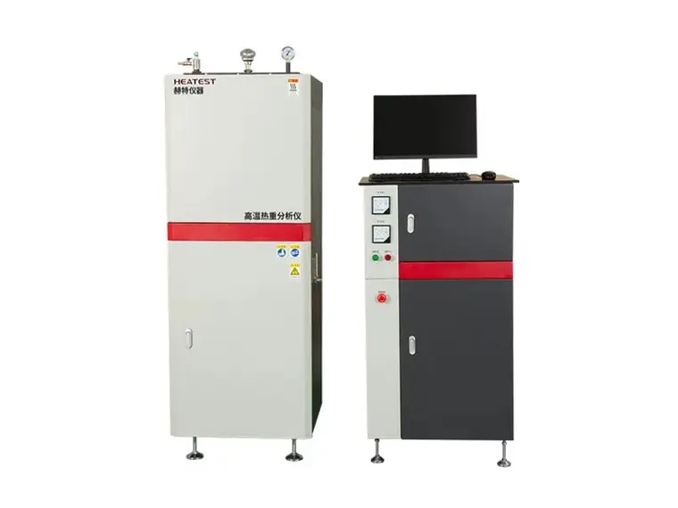
Thermogravimetric-Analyzer

Ramp rates directly affect test cycle time and throughput. For dynamic testing, you need a chamber that can heat and cool quickly without overshooting. Compare the heating rate (e.g., from 25°C to 200°C in 30 minutes) and the cooling rate (often using forced air or optional refrigeration). Some applications require rapid thermal cycling, while others prioritize stability. If your tests involve extreme temperature changes, verify the chamber’s ability to maintain accuracy during transitions. HEATEST Instrument chambers feature optimized heating elements and programmable controllers to deliver controlled ramp rates.

3. Control System and Precision

A high-quality control system distinguishes a reliable chamber from one that drifts over time. Key elements include the type of controller (PID vs. fuzzy logic), resolution, and data logging capabilities. Look for chambers that offer touchscreen interfaces, multi-step programmability, and remote monitoring via Ethernet or USB. For critical applications, demand a precision of ±0.1°C or better. The controller should also include self-diagnostics and alarm functions. HEATEST Instrument integrates industrial-grade controllers that provide both precision and user-friendly operation.

For more detailed information about high-temperature test chambers: 5 key specifications to compare before purchasing, please click here: https://www.lyheatest.com/tester-knowledge/high-temp-chamber-guide/

In thermal processing, the reliability of a muffle furnace is often judged by its ability to maintain a consistent temperature throughout the chamber. Temperature uniformity — the degree to which the temperature is the same at all points within the working zone — directly determines the quality of outcomes in applications ranging from materials testing to heat treatment. Even minor deviations can compromise experimental data, weaken product integrity, or cause batch failures. Understanding why temperature uniformity matters is essential for any professional selecting a muffle furnace, as it impacts accuracy, repeatability, and operational efficiency. This article explores the science behind uniformity, its consequences, and the criteria for choosing a furnace that delivers consistent thermal performance.

What Is Temperature Uniformity and Why Does It Matter?

Temperature uniformity refers to the maximum temperature variation measured across different locations inside the furnace chamber under stable conditions. It is usually expressed as a tolerance, such as ±5°C or ±2°C, at a given set point. While many furnace specifications highlight maximum temperature range or heating rate, uniformity is the true indicator of thermal performance. Without adequate uniformity, a furnace cannot guarantee that every sample or part receives the same thermal exposure, which is the foundation of scientific validity and industrial quality control.

For research laboratories, uniform heating ensures that experimental variables are controlled, allowing for reproducible results. In industrial settings, uniform temperature distribution prevents internal stresses, incomplete sintering, or uneven case hardening. Regulatory standards such as ASTM E145 or AMS 2750 explicitly require temperature uniformity surveys for qualification. Therefore, when a potential client evaluates a muffle furnace, uniformity specifications should be one of the primary decision-making factors.

Refractoriness-test-furnace

The Consequences of Poor Temperature Uniformity

Inadequate temperature uniformity can lead to several critical problems:

  • Invalid Test Results: In materials testing, a 5°C variation can change the phase transformation behavior of metals or the decomposition kinetics of ceramics, rendering data unreliable.
  • Product Defects: For heat-treated components, cold spots can cause insufficient hardness while hot spots may lead to over‑aging or grain growth, reducing mechanical properties.
  • Wasted Energy and Time: Operators often compensate for poor uniformity by extending soak times, which increases energy consumption and reduces throughput.

For more detailed information on why temperature uniformity is crucial for muffle furnaces, please click here: https://www.lyheatest.com/tester-knowledge/temperature-uniformity-matters-in-muffle-furnaces/

Accurate ashing tests are the backbone of quality control in food laboratories, determining mineral content and verifying product consistency. Selecting the right muffle furnace directly impacts the precision, repeatability, and efficiency of these analyses. With numerous options on the market, laboratories need a furnace that delivers uniform heating, reliable temperature control, and long-term durability. In this guide, we evaluate the critical criteria for choosing the best muffle furnace for ashing tests and explain why Heatest Instrument has become a trusted name in food lab environments.

Key Selection Criteria for Food Lab Muffle Furnaces

When choosing a muffle furnace for ashing tests, laboratory managers must consider several performance parameters that directly affect test results. The most important factors include temperature range, uniformity, ramp rate, and sample capacity.

Temperature Range and Control Precision

Standard ashing procedures for food samples typically require temperatures between 500°C and 900°C, though some matrices may need up to 1000°C. A high-quality muffle furnace should maintain ±1°C accuracy across the working zone to ensure consistent ashing. Heatest Instrument‘s furnaces feature PID controllers with real-time feedback, guaranteeing minimal temperature fluctuation even during long cycles.

Heating Uniformity and Chamber Design

Uneven heating leads to incomplete ashing and skewed results. The best furnaces employ multi-sided heating elements (typically on top, bottom, and sides) with advanced insulation to achieve uniformity of ±5°C across the entire chamber. Heatest Instrument uses high-grade ceramic fiber insulation that reduces heat loss and ensures temperature stability, critical for reproducibility in compliance with AOAC and ISO methods.

Slag-melting-temperature-tester

Advantage Comparison: Heatest Instrument vs. Generic Furnaces

To illustrate the difference that quality engineering makes, we compare Heatest Instrument’s muffle furnaces with typical budget options often found in less demanding labs.

  • Heating Element Durability: Heatest uses Kanthal A-1 wire elements embedded in ceramic plates, rated for 10,000+ hours at 1100°C. Generic furnaces often use cheaper Fe-Cr-Al wires that degrade after 2,000–3,000 hours, leading to frequent replacements.
  • Ramp/Soak Programmability: Heatest models include 8- or 16-segment programmable controllers, allowing stepwise ashing procedures (e.g., slow ramp to 250°C for volatile removal, then fast ramp to 550°C). Most basic furnaces only offer manual analog control.

For more detailed information on the best muffle furnaces for food laboratory ash testing, please click here: https://www.lyheatest.com/tester-knowledge/muffle-furnace-guide

Muffle furnaces are indispensable tools in materials testing, ashing, and heat treatment laboratories. However, their extreme operating temperatures—often exceeding 1000°C—pose serious risks of burns, fire, electrical shock, and even explosion if not handled correctly. Understanding and strictly following safety protocols is not just a recommendation; it is a fundamental responsibility for every lab technician. This article provides a comprehensive guide to muffle furnace safety, covering pre-operation checks, safe operating procedures, and post-use maintenance. Whether you work with a standard box furnace or a high-temperature model from Heatest Instrument, these tips will help you maintain a safe and efficient lab environment.

Understanding the Risks: Why Safety Matters

Before diving into procedures, it is critical to acknowledge the hazards involved. A muffle furnace operates at temperatures that can ignite combustibles, cause severe thermal injuries, and damage sensitive electronic components nearby. Common risks include:

  • Extreme heat: Direct contact with the furnace interior or heating elements can cause third-degree burns within seconds.
  • Electrical hazards: Faulty wiring, overloaded circuits, or moisture ingress can lead to short circuits or electrocution.
  • Thermal shock: Rapid temperature changes can crack refractory bricks or cause sample spattering.
  • Chemical exposure: Some materials release toxic fumes when heated; inadequate ventilation may pose respiratory risks.
  • Fire: Accumulated dust, flammable solvents, or improper sample containers can ignite inside or outside the furnace.

By recognizing these dangers, technicians can adopt a proactive mindset. Heatest Instrument designs its muffle furnaces with multiple safety features, but operator vigilance remains the first line of defense.

Essential Pre-Operation Safety Checks

Every time before using a muffle furnace, a systematic inspection should be performed. This routine minimizes preventable accidents and extends equipment life.

Inspect the Furnace and Wiring

Visually examine the furnace exterior, door seal, and power cord. Look for cracks in the refractory lining, frayed wires, or signs of overheating at the plug. Ensure the furnace is placed on a stable, non-flammable surface with adequate clearance (at least 30 cm) from walls and other equipment. For electrical safety, verify that the outlet matches the furnace rating (voltage and amperage) and that a ground fault circuit interrupter (GFCI) is present if recommended.

For more detailed information on muffle furnace safety tips that laboratory technicians should know, please click here: https://www.lyheatest.com/electric-furnace-knowledge/muffle-furnace-safety/

Muffle furnaces are essential tools in laboratories, material testing facilities, and industrial heat treatment processes. When these furnaces malfunction, even a minor issue can disrupt workflows, compromise sample integrity, or cause costly downtime. Understanding the most frequent problems and their root causes is the first step toward effective repair and maintenance. This guide outlines the common malfunctions encountered with muffle furnaces, provides clear diagnostic steps, and offers practical fixes that can be performed by trained personnel. Heatest Instrument has compiled this reference based on decades of field experience, helping users restore furnace performance quickly and safely.

Temperature Inconsistency and Drift

One of the most reported issues in muffle furnace operation is the inability to maintain a set temperature or erratic temperature readings. This problem often stems from three primary sources: faulty thermocouples, degraded insulation, or controller calibration drift.

Thermocouple Degradation

The thermocouple is the furnace’s primary temperature sensor. Over time, exposure to extreme heat and corrosive atmospheres can cause the thermocouple wires to oxidize, embrittle, or develop short circuits. A failing thermocouple typically shows temperature readings that fluctuate widely or read significantly lower than the actual temperature. Solution: Inspect the thermocouple for visible damage—discoloration, cracks, or loose connections. Replace it with a certified type-K or type-R thermocouple recommended by Heatest Instrument. After replacement, perform a two-point calibration (e.g., at 300°C and 1000°C) using a calibrated reference probe.

Insulation Deterioration

Muffle furnaces rely on high-quality ceramic fiber or refractory brick insulation to retain heat. Over many cycles, moisture absorption, thermal shock, or mechanical impact can cause cracks or compressions. This leads to heat loss, longer ramp-up times, and temperature instability. Solution: Examine the insulation inside the muffle chamber. Replace any cracked or sagging sections with Heatest Instrument’s precision-fit insulation components. Also verify that the door seals properly—gap seals are a common culprit for drift.

Controller Calibration

Even with a healthy thermocouple and insulation, an incorrectly calibrated PID controller can cause overshoot or undershoot. Solution: Access the controller’s setup menu (refer to your unit’s manual) and run an auto-tune cycle. If manual adjustment is needed, set proportional band (P), integral time (I), and derivative time (D) values based on the furnace’s thermal mass. Heatest Instrument offers downloadable PID templates for common models.

Heating Element Failure

Heating elements—typically made from Kanthal or silicon carbide—have a finite lifespan. Failure modes include open circuits, hot spots, or complete physical breakage. Symptoms include the furnace failing to reach temperature, uneven heating, or a tripped overcurrent protection device.

For more detailed information on common muffle furnace malfunctions and solutions, please click to visit: https://www.lyheatest.com/electric-furnace-knowledge/muffle-furnace-safety

Energy expenses are a significant concern for laboratories and industrial heat treatment facilities. Traditional muffle furnaces often waste thermal energy through inefficient insulation, outdated heating elements, and poor temperature control. However, modern muffle furnace designs have transformed energy consumption, offering up to 30% reduction in power usage without compromising performance. This article examines the key design innovations that lower operational costs, the specific technologies employed by Heatest Instrument, and a practical framework for evaluating furnace investments.

1. Energy Inefficiencies in Conventional Muffle Furnaces

Older muffle furnace models typically rely on ceramic fiber insulation with higher thermal conductivity, resulting in faster heat loss to the ambient environment. The heating elements, often metallic wire coils, degrade over time and require higher current to maintain set temperatures. Additionally, basic on/off temperature controllers cause thermal overshoot, wasting energy and extending cycle times. These design flaws not only increase electricity bills but also shorten furnace lifespan.

2. Modern Design Innovations That Cut Energy Costs

Advanced Insulation Materials

Contemporary furnaces use low-thermal-mass vacuum-formed ceramic fiber boards or microporous insulation. These materials reduce heat storage and loss, allowing faster heating and cooling cycles. For example, a 1200°C muffle furnace with premium insulation can reduce shell temperature by 30°C compared to standard models, translating directly to lower energy dissipation.

High-Efficiency Heating Elements

Molybdenum disilicide (MoSi2) or silicon carbide (SiC) elements offer better resistive stability and longer service life. They reach target temperature faster and maintain precise thermal output, minimizing wasted energy. Some modern designs incorporate embedded thermocouples for real-time element monitoring, preventing unnecessary energy draw.

Intelligent PID Control & Autotuning

Modern digital controllers with PID (Proportional-Integral-Derivative) algorithms and self-tuning capabilities eliminate overshoot. Power modulation reduces ON-time while maintaining ±1°C accuracy. Data logging features allow operators to optimize ramping rates and soak times, further reducing energy per batch.

For more detailed information on reducing energy costs using modern muffle furnace designs, please click here: https://www.lyheatest.com/electric-furnace-knowledge/energy-cost-muffle/

In tunnel construction, formwork assembly often represents a critical bottleneck—manual handling of heavy steel forms, sequential pouring, and extended curing periods can delay project timelines by weeks. For contractors and project managers under pressure to deliver faster, prefabricated tunnel lining solutions offer a transformative alternative. By shifting significant portions of on-site work to controlled factory environments, these systems dramatically reduce assembly time while maintaining structural integrity. This article examines the specific time-saving mechanisms of prefabricated tunnel linings and highlights how Gangda Intelligent engineered its systems to address real-world construction challenges.

The Time Challenge in Traditional Formwork Assembly

Conventional cast-in-place tunnel lining requires sequential steps: formwork positioning, reinforcement tying, concrete pouring, and a minimum of 12–24 hours of curing before striking. Each cycle consumes manpower and exposes the schedule to weather delays.

Labor-Intensive and Weather-Dependent

Typical formwork crews of 6–8 workers spend up to 40% of shift time on manual alignment and fastening. Rain or low temperatures can halt pours, pushing curing times unpredictably. These variables make accurate schedule forecasts nearly impossible.

Sequential Process Delays

Because each section must be poured and cured before the next formwork can be moved, the critical path lengthens linearly. For a 1 km tunnel section, traditional methods often require 90–120 days purely for the lining phase.

How Prefabricated Tunnel Lining Solutions Cut Assembly Time

Prefabricated linings, such as those offered by Gangda Intelligent, eliminate most on-site formwork operations. Key time-saving factors include:

  • Factory pre‑assembly accuracy: Sections are cast in precise molds, ensuring fit tolerances of ±2 mm, which enables rapid bolting on site without adjustment.
  • Minimized wet trades: Only joint sealing and minor grouting remain, cutting the curing queue from days to hours.
  • Parallel production: While one tunnel segment is being installed, the next is already curing in the factory, decoupling production from on‑site conditions.
  • Simplified logistics: Lightweight modular panels (typically 2–4 tons each) can be handled by a single excavator or gantry, reducing crew size by 40%.

On typical metro or highway tunnels, these improvements can shrink the lining schedule by 50–60% compared to cast‑in‑place methods.

For more details on saving formwork assembly time: Precast tunnel lining solutions, please click to visit: https://www.gdtunnel.com/a/blog/tunnel-lining-time-savings.html

Tunnel lining formwork is a critical component in underground construction, directly influencing structural integrity, construction speed, and cost efficiency. Whether you are working on railway tunnels, metro systems, or hydraulic projects, the cross-sectional shape of the tunnel—circular, horseshoe, or rectangular—dictates the specific formwork system required. This comprehensive guide explores the unique characteristics, design considerations, and application scenarios for each shape, providing you with the knowledge to make an informed procurement decision.

Circular Tunnel Lining Formwork: Precision in Radial Geometry

Circular cross-sections remain the most common in tunneling due to their exceptional load distribution and hydraulic performance. The formwork system for circular tunnels must achieve high geometric accuracy to ensure uniform concrete thickness and watertightness.

Key Design Features

  • Full-round telescopic formwork: Typically segmented into two or more telescopic panels that retract radially for striking and advance for pouring.
  • Adjustable diameter range: Quality systems allow for ±5% diameter adjustment to compensate for over/under excavation.
  • Hydraulic operation: Powered by synchronized hydraulic cylinders for uniform movement and reduced cycle time.
  • End sealing system: Effective grout seals at both ends to prevent leakage during high-pressure concreting.

Circular formwork excels in projects with high internal water pressure or variable ground conditions. The continuous curved surface eliminates stress concentrations, making it ideal for deep tunnels and subaqueous crossings.

Horseshoe Tunnel Lining Formwork: Optimizing Space for Utilities

The horseshoe shape—essentially a circular arch with vertical sidewalls and an invert—offers a compromise between structural efficiency and usable floor area. It is widely adopted in railway and highway tunnels where space for ventilation, walkways, and equipment is essential.

Formwork Configurations

Horseshoe lining formwork typically comprises three main components: the arch crown form, sidewall forms, and invert form. Advanced systems integrate these elements into a single traveling gantry that moves on rails, enabling rapid sequential pouring. Key considerations include:

  • Arch-to-sidewall transition: The geometry requires careful planning to avoid cold joints. Gangda Intelligent’s continuous pour system eliminates intermediary construction joints.
  • Variable width adaptability: Many projects use multiple horseshoe widths within the same alignment. A modular formwork system with interchangeable arch segments provides cost-effective flexibility.
  • Invert integration: The curved invert section demands robust formwork that can withstand concrete pressure while maintaining profile accuracy.

Compared to circular sections, horseshoe tunnels provide approximately 15–25% more usable cross-sectional area for the same excavation volume, making them a favorite for transportation tunnels.

Rectangular Tunnel Lining Formwork: Maximizing Clear Span for Infrastructure

Rectangular sections are prevalent in cut-and-cover tunnels, underground metro stations, and pedestrian underpasses. Their flat surfaces simplify alignment of equipment and optimize space utilization. However, the sharp corners introduce stress concentrations that require robust formwork design.

For more information on the complete guide: Circular, Horseshoe, and Rectangular Section Tunnel Lining Formwork, please click here: https://www.gdtunnel.com/a/blog/tunnel-lining-guide.html