Thin section four-point contact bearings have become an indispensable component in precision machinery, aerospace applications, robotics, and other high-performance systems. Their compact size combined with high load-carrying capacity makes them ideal for applications where space is limited but performance cannot be compromised. Understanding how to calculate load capacity for thin section four-point contact bearings is critical for engineers and designers to ensure system reliability, longevity, and optimal performance.
Understanding the Basics of Thin Section Four-Point Contact Bearings

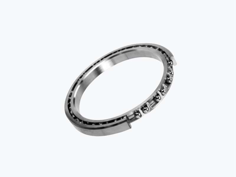
Thin section four-point contact bearings are unique because they are designed to accommodate axial loads in both directions, in addition to radial loads. Unlike standard ball bearings, these bearings distribute loads across four points of contact, which reduces stress concentration and improves rigidity. They are often used in robotic joints, rotary tables, and optical equipment where precise motion control is essential.
The calculation of load capacity is influenced by several factors, including the bearing’s geometry, material properties, preload, and operational environment. By carefully analyzing these factors, engineers can select the appropriate bearing size and ensure that it operates safely within its design limits.
Key Factors Affecting Load Capacity
Before diving into the calculations, it is important to identify the primary factors that affect the load capacity of thin section four-point contact bearings:
Bearing Geometry: The inner and outer ring diameters, cross-section width, and contact angle directly influence the load distribution and stress levels within the bearing. A larger cross-section and higher contact angle typically increase load capacity.
Material Strength: Bearings made from high-quality, hardened steel or advanced ceramics can sustain higher loads compared to those made from standard materials. Material fatigue limits must be considered when calculating load capacity for long-term operation.
Preload Conditions: Applying proper preload can enhance stiffness and reduce deflection. However, excessive preload may increase friction and heat generation, reducing bearing life.
Operating Environment: Temperature, lubrication, and contamination impact the effective load capacity. Bearings operating in high-temperature or contaminated environments require derating factors to account for reduced performance.
Dynamic vs. Static Loads: The bearing load capacity differs for dynamic (rotating) versus static (stationary) applications. Dynamic capacity considers fatigue life under repeated loading cycles, whereas static capacity focuses on the bearing’s ability to withstand peak loads without permanent deformation.
…
For more detailed information on the calculation of the load capacity of thin-section four-point contact bearings, please click to visit:https://www.prsbearings.com/a/news/calculation-of-the-load-capacity-of-thin-section-four-point-contact-bearings.html