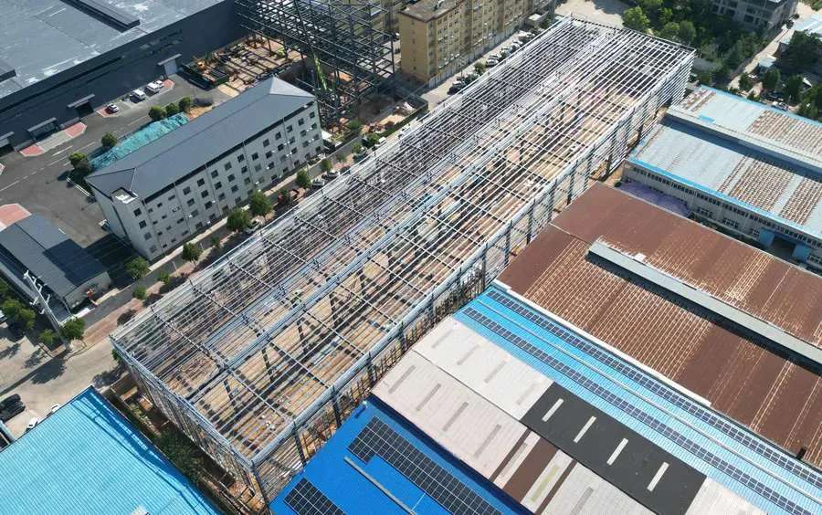
In modern civil engineering and urban infrastructure projects, the construction of tunnels presents unique challenges that demand both precision and speed. Traditional construction methods often require extensive scaffolding, repetitive formwork setups, and considerable labor hours. As urban areas expand and transportation networks become more complex, the need for efficient, safe, and cost-effective tunnel construction solutions has never been greater. This is where concrete tunnel formwork comes into play, revolutionizing the way engineers approach tunnel construction.

What is Concrete Tunnel Formwork?

Concrete tunnel formwork is a specialized system designed to shape and support concrete until it hardens, allowing for the rapid and accurate construction of tunnel segments. Unlike conventional formwork, tunnel formwork is typically modular and reusable, tailored to fit the geometric profile of the tunnel, whether circular, horseshoe-shaped, or rectangular. This precision ensures that the final structure meets both design specifications and safety standards.

One of the core advantages of tunnel formwork lies in its adaptability. Engineers can pre-fabricate the forms off-site, ensuring uniform quality, and then transport them to the construction site for assembly. This approach minimizes on-site errors and significantly reduces construction timelines.

Key Advantages of Using Concrete Tunnel Formwork

Enhanced Construction Speed

Traditional tunnel construction often requires multiple steps, including building scaffolds, setting up timber forms, and manually supporting concrete during curing. Concrete tunnel formwork simplifies these steps by combining shaping and support into a single system, enabling continuous casting cycles. In practice, this can reduce the construction period by up to 30–50%, which is critical for projects operating under tight deadlines.

Improved Structural Quality

The uniformity provided by pre-engineered tunnel forms ensures consistent concrete thickness, smooth surface finishes, and precise alignment. Reduced human error during assembly translates to fewer defects, such as uneven walls or misaligned segments, enhancing long-term structural durability and reducing maintenance costs.

Cost Efficiency

While the initial investment in concrete tunnel formwork systems can be higher than traditional methods, the long-term savings are substantial. Reusable modular forms lower labor costs, minimize material waste, and accelerate project timelines. For large-scale infrastructure projects like metro tunnels or hydropower conduits, these savings can be significant, effectively improving the return on investment.

Enhanced Safety on Site

Tunnel construction is inherently hazardous, with risks ranging from structural collapse to worker fatigue due to repetitive tasks. Concrete tunnel formwork reduces these hazards by offering stable, pre-engineered components that minimize on-site adjustments and repetitive manual labor. Workers can operate within safer, more predictable environments, reducing the likelihood of accidents.

Concrete Tunnel Formwork

Applications in Modern Tunnel Projects

Concrete tunnel formwork is particularly valuable in projects that require high-speed urban tunneling. Metro rail systems, underground pedestrian passages, sewage and water pipelines, and vehicular tunnels all benefit from the precision and speed provided by these systems. Additionally, specialized forms can accommodate complex tunnel geometries, including curved alignments, branching segments, and variable diameters, making them highly versatile for diverse civil engineering challenges.

Beyond transportation, concrete tunnel formwork has also found applications in energy and utility projects. Hydropower tunnels, geothermal channels, and underground utility conduits benefit from the repeatable precision of modular formwork systems, which ensure accurate flow paths and structural integrity over long spans.

For more detailed information on efficient concrete tunnel formwork solutions suitable for modern tunnel construction, please click to visit: https://www.gf-bridge-tunnel.com/a/blog/concrete-tunnel-formwork-solutions-for-modern-tunnel-construction.html

In modern mining, quarrying, and aggregate processing operations, cone crushers have become indispensable equipment for secondary and tertiary crushing. These machines are expected to operate continuously under harsh working conditions, handling abrasive materials and fluctuating loads. At the core of this performance lies a critical yet often underestimated subsystem—the hydraulic system.

The hydraulic system does far more than simply support crusher movement. It directly influences operational stability, product quality, and equipment safety. When hydraulic failures occur, they rarely affect just one function; instead, they often trigger a chain reaction that leads to unplanned downtime, reduced throughput, and increased maintenance costs.

For plant managers, maintenance engineers, and equipment operators, understanding how to diagnose and resolve hydraulic system failures is not only a technical requirement but also a key factor in improving overall production efficiency. This guide provides a comprehensive, experience-driven overview of common hydraulic issues in cone crushers and offers practical troubleshooting strategies based on real-world operating conditions.

The Critical Role of Hydraulic Systems in Cone Crushers

A cone crusher’s hydraulic system serves as the control center for several essential functions, and each function directly impacts production performance.

First, the hydraulic system regulates the discharge opening. By precisely adjusting the closed-side setting (CSS), operators can control product size distribution and ensure consistent output quality. Any deviation in hydraulic response can result in uneven particle size, which affects downstream processes.

Second, the system provides overload protection. When uncrushable materials such as metal fragments enter the crushing chamber, the hydraulic system allows the main shaft to retract temporarily, preventing catastrophic damage to internal components. Without this protection, a single incident could lead to costly repairs and extended downtime.

Third, the hydraulic circuit supports lubrication and cavity clearing. Proper lubrication reduces friction and wear, while hydraulic clearing systems help remove blockages quickly, minimizing production interruptions.

Because these functions are interconnected, even a minor hydraulic issue—such as a partially clogged filter or slight pressure instability—can escalate into serious operational problems if not addressed promptly.

Common Hydraulic System Failures and Their Root Causes

Cone Crushers

1. Low Pressure or Pressure Instability

In daily operation, insufficient hydraulic pressure or fluctuating pressure is one of the most frequently reported issues. This problem often develops gradually, making it difficult to detect in its early stages.

Typical causes include internal wear in hydraulic pumps, leakage in valves or pipelines, clogged filters, or air entering the system. When pressure drops below the required level, the crusher may fail to adjust its setting accurately or respond properly to overload conditions. On the other hand, sudden pressure spikes can damage seals, accelerate component fatigue, and increase the risk of system failure.

Operators often notice delayed adjustment response or inconsistent crushing performance as early warning signs.

For more detailed information on troubleshooting common hydraulic system faults in cone crushers, please click to visit: https://www.yd-crusher.com/a/news/troubleshooting-common-hydraulic-system-failures-in-cone-crushers.html

In modern mining and aggregate processing environments, the reliability of cone crusher equipment directly determines production efficiency and cost control. Among all critical components, the mantle and concave liners in a cone crusher play a decisive role in shaping output quality, throughput stability, and maintenance frequency. These wear parts operate under continuous high-pressure crushing conditions, often handling abrasive and irregular materials, which makes their degradation unavoidable over time.

However, premature wear is not simply a matter of material fatigue—it is often the result of operational inefficiencies, improper configuration, or overlooked maintenance details. For plant managers and engineers aiming to reduce downtime and improve return on investment, extending the service life of mantles and liners is a strategic priority rather than a routine task.

How to Extend the Lifespan of Cone Crusher Mantles and Liners

This guide explores practical, field-tested methods to enhance wear part longevity while aligning with modern industrial best practices and performance expectations.

cone crusher

A Deeper Look at Wear Mechanisms in Cone Crushers

To effectively extend component lifespan, it is essential to understand how and why wear occurs. In a cone crusher, the mantle performs a gyratory motion inside the concave liner, compressing material against a stationary surface. This process generates two primary types of wear:

Abrasive wear, caused by hard particles continuously grinding against the surface

Impact wear, resulting from large or uneven feed materials striking the liners

The rate at which these wear mechanisms occur depends on multiple interacting variables:

The hardness, moisture content, and silica composition of the processed material

The consistency and gradation of feed entering the crushing chamber

The mechanical setup, including eccentric throw and chamber configuration

The metallurgical properties of the wear parts themselves

A clear understanding of these factors allows operators to move from reactive replacement to proactive lifecycle management.

Precision Installation: The Foundation of Wear Life

For more detailed information on how to extend the service life of cone crusher liners and bucket plates, please click to visit: https://www.yd-crusher.com/a/news/how-to-extend-the-lifespan-of-cone-crusher-mantles-and-liners.html

In the world of mineral processing and aggregate production, “shape” is not just an aesthetic preference—it is a rigorous technical requirement. Whether you are supplying high-strength concrete for skyscrapers or durable asphalt for highway infrastructure, the cubicity of your crushed stone determines its interlocking capability, cement consumption, and overall structural integrity.

The cone crusher is the workhorse of secondary and tertiary crushing, prized for its efficiency. However, many operators fall into the trap of believing that the machine alone dictates the output. In reality, achieving a high-quality, uniform product is a symphony of mechanical precision, material science, and operational strategy. This comprehensive guide dissects the top five critical factors that define product shape and offers actionable insights to transform your crushing circuit into a high-value production line.

Factors affecting the particle shape of the finished product from cone crusher

cone crusher

1. Feed Material Characteristics

The properties of the raw material entering a cone crusher have a profound effect on the product shape. Key characteristics include hardness, moisture content, particle size distribution, and mineral composition. Hard and abrasive materials, such as granite or basalt, require careful adjustment of crusher parameters to avoid producing excessive fines or elongated particles. Similarly, moisture content can cause material to stick to the crushing surfaces, leading to irregular shapes and clogging. Ensuring a consistent feed size and avoiding oversized lumps helps in achieving uniform crushing and reduces wear on the cone liners.

2. Crushing Chamber Design

Cone crushers feature different types of crushing chambers, commonly classified as standard, medium, and short head designs. Each design influences the crushing action, material flow, and contact points within the chamber. A standard chamber is typically suited for secondary crushing and tends to produce more cubic-shaped particles, whereas a short head design is used for finer tertiary crushing, which may result in slightly elongated particles if not properly managed. Selecting the right chamber type based on the target product size and application is essential for controlling particle shape and maximizing production efficiency.

For more detailed information on factors affecting the shape of finished particles from a cone crusher, please click to visit: https://www.yd-crusher.com/a/news/factors-affecting-the-particle-shape-of-the-finished-product-from-cone-crusher.html

Cone crushers are the backbone of crushing operations in mining, quarrying, and aggregate production. They are designed to handle hard, abrasive materials such as granite, iron ore, and limestone, reducing them into smaller, manageable sizes. One of the most critical components ensuring smooth, reliable operation is the bronze bushing. These bushings act as the interface between the rotating mantle and the stationary concave, supporting heavy loads while enabling precise rotational movement. Over time, intense pressure, high friction, and abrasive materials gradually wear the bushings. Failure to replace them correctly can lead to uneven crushing, excessive vibration, or even catastrophic damage to the crusher. This guide provides a comprehensive, step-by-step approach to replacing cone crusher bronze bushings, ensuring operational safety, efficiency, and long-term equipment reliability.

Why Bronze Bushings Are Vital for Cone Crusher Performance

Bronze bushings serve as the bearing surface between the crusher’s mantle and concave. High-strength bronze alloys are typically used due to their excellent wear resistance, ability to absorb impact, and compatibility with the metal-to-metal contact inherent in cone crushers. Proper installation is crucial: even minor misalignment or inadequate lubrication can accelerate wear, reduce crushing efficiency, and place undue stress on other components such as the main shaft, eccentric assembly, and frame. Understanding their role helps operators appreciate why meticulous replacement procedures are non-negotiable for maintaining production quality and minimizing downtime.

Steps for Replacing Cone Crusher Bronze Bushings

Cone Crusher

Step 1: Prepare the Crusher for Maintenance

Before performing any maintenance, safety is paramount. Begin by shutting down the crusher completely and disconnecting the power supply. Release any stored hydraulic or mechanical pressure to prevent sudden movements. Equip your team with personal protective equipment (PPE), including gloves, safety goggles, steel-toed boots, and hard hats. Clear the work area of loose material, tools, and debris to create a safe and organized workspace. Ensure lifting equipment such as cranes, hoists, or jacks is rated for the weight of the mantle and other heavy components. Proper preparation reduces the risk of injury and ensures the replacement process proceeds smoothly.

For more detailed information on how to properly replace bronze bushings in a cone crusher, please click to visit: https://www.yd-crusher.com/a/news/steps-for-replacing-cone-crusher-bronze-bushings.html

In modern industrial systems where precision, compact design, and high efficiency are essential, thin section bearings have become a critical component across a wide range of applications. From industrial robotics and semiconductor equipment to aerospace assemblies and medical devices, these bearings support smooth motion while maintaining strict dimensional constraints.

However, many equipment failures do not originate from design flaws, but from inadequate maintenance practices. Among these, improper cleaning and lubrication remain one of the most common causes of premature bearing failure. This guide provides a comprehensive, practical, and experience-driven approach to cleaning and re-greasing thin section bearings, helping maintenance teams extend service life, reduce downtime, and improve overall equipment performance.

What Makes Thin Section Bearings Unique?

Thin Section Bearings

Thin section bearings are specifically engineered to deliver high load capacity within a minimal cross-sectional profile. Unlike conventional bearings, their thin-walled structure allows engineers to reduce overall system weight and size without compromising rotational accuracy.

Manufacturers typically use these bearings in applications such as:

Precision rotary tables

Industrial robot joints

Aerospace positioning systems

Automated inspection equipment

Medical imaging devices

While this compact design offers clear advantages, it also introduces certain vulnerabilities. The reduced cross-section makes these bearings more sensitive to contamination, lubrication degradation, and installation errors. Even small particles or insufficient lubrication can quickly affect performance, leading to increased torque, vibration, and wear.

Why Proper Cleaning and Re-Greasing Is Critical

For more detailed information on cleaning and relubricating guidelines for thin-section bearings, please click here: https://www.lynicebearings.com/a/blog/guide-to-cleaning-and-re-greasing-thin-section-bearings.html

In modern high-precision equipment design, thin section ball bearings are no longer a niche component—they have become a strategic choice in industries where space, weight, and performance must be optimized simultaneously. From aerospace actuation systems and robotic joints to medical imaging devices and semiconductor equipment, these bearings enable engineers to achieve compact architectures without sacrificing rotational accuracy.

However, the same design characteristics that make thin section ball bearings highly efficient—reduced cross-section, lightweight construction, and tight tolerances—also make them more sensitive to real-world operating conditions. In practical applications, premature failure is rarely accidental; it is typically the result of overlooked details in lubrication, installation, load management, or environmental control.

Causes of Premature Failure in Thin Section Ball Bearings

thin section ball bearings

This article does not simply list common causes. Instead, it provides a deeper, experience-driven analysis of why failures occur, how they develop over time, and what engineers and maintenance teams can do to prevent them in real operating environments.

1. Lubrication Deficiency: A Subtle but Critical Failure Trigger

In theory, lubrication is straightforward. In practice, it is one of the most misunderstood aspects of thin section bearing performance.

Due to their slim geometry, thin section ball bearings have limited internal space for lubricant retention. This means that unlike conventional bearings, they cannot rely on large grease reservoirs to compensate for suboptimal lubrication practices. Once the lubricant film breaks down, direct metal contact begins almost immediately.

The issue is not always a lack of lubricant—it is often incorrect lubrication strategy. For example, selecting a grease with inappropriate viscosity for high-speed applications can lead to excessive shear heating, accelerating degradation. Similarly, in low-speed but high-load environments, insufficient film thickness can cause micro-welding between contact surfaces.

Temperature also plays a critical role. In applications such as robotics or automated production lines, continuous operation leads to gradual heat buildup. Over time, this alters lubricant properties, reducing its ability to maintain a stable film between rolling elements and raceways.

For more detailed information on the causes of premature failure in thin-section ball bearings, please click to visit: https://www.lynicebearings.com/a/blog/causes-of-premature-failure-in-thin-section-ball-bearings.html

Thin section bearings are an essential component in modern mechanical design, offering compact solutions for applications where space is limited, yet performance cannot be compromised. From robotics and aerospace assemblies to medical devices and precision machinery, these bearings enable smooth rotation and high load capacity within minimal space. However, choosing the right material for thin section bearings is crucial, especially when considering corrosion resistance and long-term reliability. In this guide, we compare stainless steel and chrome steel thin section bearings, highlighting their corrosion resistance characteristics and providing actionable insights for engineers, designers, and procurement specialists.

Before diving into material comparisons, it is important to understand what makes thin section bearings unique. Unlike standard bearings, thin section bearings have a reduced cross-section, allowing designers to achieve space-saving solutions without compromising rotational accuracy. These bearings are commonly available in radial, angular contact, and precision series, and are made to support moderate to heavy loads while maintaining minimal thickness.

Due to their compact nature, thin section bearings often operate in environments where moisture, chemicals, or contaminants may be present. Consequently, corrosion resistance becomes a critical factor in material selection.

Corrosion Protection Guidelines for Thin-Walled Bearings

Thin section bearings

Chrome Steel Thin Section Bearings

Chrome steel, also known as high-carbon chromium steel (commonly AISI 52100), is one of the most widely used materials for bearings. Chrome steel offers exceptional hardness, wear resistance, and fatigue life, making it a reliable choice for many high-performance applications. Its main advantages include:

High load capacity: Chrome steel provides excellent contact fatigue resistance, which allows it to handle heavy radial and axial loads.

Durability: Chrome steel is highly wear-resistant and maintains precise tolerances over extended operating periods.

Cost-effectiveness: Compared to specialty steels, chrome steel is generally more affordable, making it ideal for mass production.

For more detailed information on whether stainless steel or chrome steel should be used for thin-section bearings in corrosive environments, please click to visit: https://www.lynicebearings.com/a/blog/corrosion-protection-guidelines-for-thin-walled-bearings.html

In the realm of modern mechanical engineering, thin section bearings have emerged as indispensable components for high-speed, precision-driven applications. From aerospace actuators and robotic joints to industrial automation systems, these bearings offer a compact yet robust solution where conventional bearings would be too bulky or heavy. Characterized by their reduced cross-sectional thickness while maintaining substantial load-carrying capacity, thin section bearings excel in scenarios with stringent space and weight limitations. However, despite their advantages, engineers frequently encounter challenges in accurately determining the torque requirements under high-speed conditions—a critical factor that, if mismanaged, can trigger excessive friction, accelerated wear, vibration issues, and ultimately, operational inefficiencies that compromise performance and reliability.

Understanding the Role of Thin Section Bearings in High-Speed Systems

Thin section bearings differ from traditional bearings primarily in their slender profile, which allows for integration into compact mechanical assemblies without sacrificing rigidity or load capacity. Their lightweight construction makes them especially suitable for high-speed rotations, precision alignment, and applications where the bearing envelope directly impacts the overall system design. Common use cases include satellite positioning systems, high-speed turntables in optical or semiconductor equipment, precision medical imaging devices, and automated manufacturing machinery, where every millimeter and gram counts.

Yet, the very design that makes thin section bearings advantageous also renders them more sensitive to torque-related issues. Reduced material volume can amplify heat generation, frictional forces, and mechanical stress under dynamic loads, meaning that even small miscalculations can have outsized consequences. High-speed operation introduces additional complexities, including centrifugal forces, fluctuating dynamic loads, lubrication film instability, and thermal expansion. Therefore, a detailed, methodical approach to torque calculation is not merely advisable—it is essential for ensuring operational efficiency and longevity.

thin section bearings

Critical Factors in Torque Estimation for High-Speed Bearings

Accurate torque calculation for thin section bearings in demanding applications requires consideration of multiple, interrelated factors:

Friction Torque: Friction is the primary resistance a bearing faces during rotation, influenced by bearing type, internal clearances, lubrication characteristics, and rotational speed. While manufacturers provide baseline friction coefficients, these figures often assume ideal conditions. In practice, temperature variations, contamination, and misalignment can dramatically alter frictional behavior, necessitating adjustments in torque estimation.

For more detailed information on optimizing the torque of thin-section bearings for high-speed applications, please click to visit: https://www.lynicebearings.com/a/blog/thin-section-bearing-torque-calculation-for-high-speed-applications.html

Crossed roller bearings play a critical role in modern precision machinery. Engineers widely select this type of bearing for applications that demand high rigidity, compact structure, and exceptional rotational accuracy. Industries such as robotics, CNC machine tools, semiconductor equipment, and heavy-duty rotary platforms rely heavily on crossed roller bearings to ensure stable and precise motion.

However, many operators encounter a frustrating issue during actual use: uneven, jerky, or inconsistent rotation. This problem not only affects equipment accuracy but may also lead to vibration, noise, premature wear, and even unexpected downtime. For businesses that depend on high-precision operations, such performance instability can directly impact productivity and operating costs.

Troubleshooting Guide for Uneven Rotation of Crossed Roller Bearings

This article provides a comprehensive and practical analysis of why crossed roller bearings rotate unevenly, along with actionable troubleshooting methods and preventive strategies. By understanding these factors in depth, maintenance teams and engineers can significantly improve equipment reliability and extend bearing service life.

Crossed Roller Bearings

1. How Crossed Roller Bearings Work and Why Precision Matters

A crossed roller bearing features cylindrical rollers arranged alternately at 90-degree angles between the inner and outer rings. This unique structure allows a single bearing to simultaneously handle radial loads, axial loads, and overturning moments.

Unlike conventional ball bearings, crossed roller bearings depend heavily on:

Precise geometric alignment

Controlled preload settings

Uniform load distribution across all rollers

Because of this design sensitivity, even minor deviations during installation or operation can lead to uneven load sharing among rollers. Once the load distribution becomes unbalanced, the bearing will no longer rotate smoothly, and localized stress concentrations will begin to develop.

Therefore, when uneven rotation occurs, it often indicates deeper issues related to installation accuracy, lubrication condition, or working environment rather than a simple surface-level fault.

2. Key Causes of Uneven Rotation in Crossed Roller Bearings

2.1 Installation Misalignment

Improper alignment during installation remains one of the most common causes of uneven rotation. When technicians fail to align the inner and outer rings precisely, some rollers are forced to carry excessive loads while others remain underutilized.

For more detailed information on troubleshooting uneven rotation of crossed roller bearings, please click to visit: https://www.prsbearings.com/a/news/troubleshooting-guide-for-uneven-rotation-of-crossed-roller-bearings.html