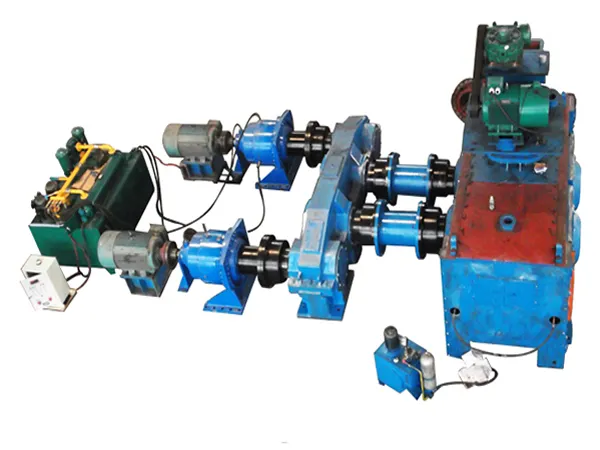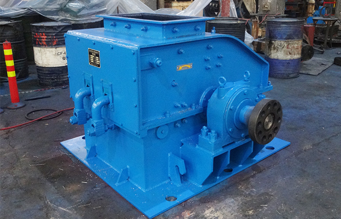
Small workshops entering the wind tower fabrication market often face a dilemma: high-performance welding rotators are essential for efficient and consistent seam welding, yet most industrial-grade machines carry price tags and footprint requirements that are prohibitive for a limited budget and floor space. A cost-effective wind tower welding rotator bridges this gap, delivering the precision, load capacity, and rotational control needed for tower sections without demanding the capital investment of full-scale automation. For workshops seeking to expand their capabilities without overextending resources, choosing the right rotator can mean the difference between turning away tower contracts and building a profitable niche.

Understanding the Need: Why Small Workshops Require Specialized Welding Rotators

The Challenge of Large-Scale Equipment in Small Spaces

Wind tower sections are large and heavy—often exceeding 10 tons for smaller diameter segments. Traditional welding rotators designed for mega-factories assume unlimited floor space and high-voltage three-phase power. Small workshops typically operate in tighter facilities with single-phase or limited three-phase supply, making conventional rotators impractical. Additionally, the upfront cost of a 20-ton rotator from major industrial suppliers can easily surpass $50,000, a sum that is difficult for a small business to allocate.

Balancing Cost and Performance

A cost-effective unit must offer enough torque and rotation speed to handle tower pipe diameters from 1.5 meters up to 4.5 meters, while keeping the purchase price under $15,000. This requires smart engineering: using robust but standard components, efficient drive systems, and modular designs that allow future upgrades. Small workshops do not need the extreme precision of robotic interfaces—they need reliable rotation that supports consistent weld quality at a moderate production rate.

Key Features of a Cost-Effective Wind Tower Welding Rotator

When evaluating rotators for small workshop use, focus on features that directly impact productivity and total cost of ownership:

  • Compact footprint – The rotator should occupy no more than 2 meters in length, allowing easy integration into existing layout.
  • Adjustable wheel spacing – To accommodate different tower diameters without requiring multiple units.
  • Variable speed control with digital readout – Enabling precise rotational speed adjustment (0.1–1.5 rpm) for different wall thicknesses.
  • Self-locking drive system – Prevents backlash and ensures safety when welding in fixed positions.
  • Modular construction – Allows adding a second driven wheel set later if load capacity needs to increase.
  • Easy maintenance – Greasable bearings, accessible gearboxes, and standard replacement parts.

Click here for more details on economical wind tower welding rotators suitable for small workshops: https://www.bota-weld.com/en/a/news/cost-effective-rotator.html

Welding defects in tower sections remain one of the most costly and time-consuming challenges in wind turbine manufacturing. Inconsistent penetration, porosity, and distortion not only increase rework expenses but also compromise the long-term structural integrity of towers. A proven solution lies in synced rotation—coordinating the rotational speed of the tower section with the welding torch movement. When implemented correctly, this technique eliminates uneven heat distribution, reduces residual stress, and ensures uniform weld bead geometry. BOTA has developed advanced turnkey systems that make synced rotation practical and repeatable for production environments.

The Critical Impact of Weld Defects in Tower Section Manufacturing

Tower sections are among the largest and most heavily loaded components in a wind turbine. A single defect—such as lack of fusion, undercut, or centerline cracking—can lead to premature fatigue failure. The consequences include costly field repairs, extended downtime, and potential safety risks. In high-volume fabrication, even a minor defect rate of 2% can translate into hundreds of hours of grinding, welding, and inspection labor per year. The welding process itself introduces thermal cycles that vary with section thickness, joint design, and heat input. Traditional static welding (where the section remains fixed while the welding head moves) inherently creates an asymmetric thermal profile: the lead side of the weld pool experiences different cooling rates than the trailing side. This asymmetry is a primary driver of angular distortion, excessive convexity, and incomplete sidewall fusion.

By contrast, synced rotation aligns the axis of welding travel with the part rotation, making the heat input symmetrical around the circumference. This simple yet powerful change addresses the root cause of many common defects.

How Synced Rotation Eliminates Common Weld Defects

The key mechanism behind synced rotation is the elimination of the relative motion between the welding torch and the workpiece that occurs in the “orbital” or “fixed-torch” methods. In a typical orbital welding setup, the torch moves around a stationary cylinder, constantly changing its angle relative to gravity. This variation alters the puddle shape and can lead to sagging or unstable arc behavior. Synced rotation, on the other hand, keeps the torch fixed in the 12 o’clock or 2 o’clock position while the tower section rotates beneath it. The result is a consistent working angle and a stable molten pool throughout the entire weld pass.

Uniform Heat Input and Controlled Cooling

When the section rotates at a constant speed matched to the desired travel speed, every point on the weld joint experiences the same heat input per unit length. This uniformity directly reduces the risk of hot cracking (which occurs when the cooling rate is too fast) and brittle zones (caused by slow cooling). The controlled rotation also allows the use of higher deposition rates without sacrificing quality, because the heat can be better managed. BOTA’s precision rotation controllers maintain rotational speed within ±0.1% of setpoint, ensuring repeatable bead geometry across hundreds of sections.

For more detailed information on reducing welding defects in tower sections through synchronous rotation, please click here: https://www.bota-weld.com/en/a/news/weld-defects-reduction.html

Wind tower sections demand welding precision that conventional fixed-speed rotators cannot deliver. As tower diameters and wall thicknesses vary across segments, the rotation speed must adapt to maintain consistent weld pool control, heat input, and penetration. Without variable speed control, operators face frequent adjustments, increased rework, and compromised structural integrity. Understanding why variable speed matters—and how it directly impacts weld quality, cycle time, and safety—is essential for any fabricator investing in wind tower production equipment. This article explains the technical rationale and practical benefits of variable speed, with insights from BOTA’s engineering experience.

The Critical Role of Variable Speed in Welding Quality

In multi-pass welding of wind tower sections, each pass requires a different travel speed to achieve the desired bead shape and fusion. Fixed speed systems force the operator to either accept a compromised setting or stop to manually change gears or belts—both of which introduce inconsistency. Variable speed control enables real-time adjustment of rotation rate, allowing the welder to match the exact linear welding speed needed for each pass, even as the workpiece diameter increases or decreases.

For example, the root pass on a thick-walled tower base often demands slower rotation to allow complete fusion, while fill and cap passes can run faster. With a variable speed drive, the operator can dial in the precise speed without leaving the welding station. This reduces the risk of common defects such as lack of fusion, undercut, and excessive reinforcement. Consistent welding speed directly correlates to uniform mechanical properties across the entire circumferential seam—a critical requirement for fatigue resistance in wind turbine towers.

Heat Input Control

Heat input is a function of arc voltage, current, and travel speed. When the rotator speed fluctuates or remains fixed at a suboptimal value, the heat input per unit length varies. Variable speed control allows the fabricator to maintain a targeted heat input range, which is essential for achieving the specified microstructure and minimizing distortion. BOTA’s rotators use closed-loop speed regulation to hold the set speed within ±1% deviation, even under heavy loads.

Adapting to Real-World Production Variables

wind tower welding rotators

Wind tower fabrication involves frequent changes in workpiece geometry and weight. A single tower consists of multiple cans with different diameters—ranging from 4 meters at the base to 2.5 meters at the top—and each weld joint may be in a flat, horizontal, or vertical-up position depending on the tower orientation during assembly. Variable speed gives the operator the flexibility to adjust for these variables without mechanical changes.

When welding a long seam on a large-diameter section, the linear surface speed changes as the rotator turns. A constant rotator RPM yields a faster linear speed on larger diameters and slower on smaller ones. With variable speed, the welder can set the linear speed directly (e.g., 25 cm/min) and rely on the drive controller to automatically adjust RPM as the diameter changes. This is especially valuable for automated welding systems where travel speed must remain constant for consistent arc behavior.

Click here for more details on why variable speed control is crucial for wind tower welding rotators: https://www.bota-weld.com/en/a/news/variable-speed-rotators.html

When selecting a welding rotator for wind tower fabrication, the choice between pneumatic and electric drive systems is a critical decision that affects production efficiency, operational cost, and weld quality. Both technologies have distinct advantages and limitations, especially in the demanding context of large-diameter tower sections. This article provides a data-driven comparison of pneumatic vs electric wind tower welding rotators, highlighting performance metrics, maintenance requirements, and total cost of ownership. By the end, you will have clear criteria to determine which system aligns with your production goals, with practical insights informed by BOTA’s extensive field experience.

Fundamental Differences in Drive Mechanics

Pneumatic rotators use compressed air to power a rotary vane or piston motor, while electric rotators rely on alternating current (AC) or direct current (DC) motors with gear reducers. The underlying physics dictates their performance envelopes.

Pneumatic Rotators

  • Torque characteristics: Pneumatic motors deliver high starting torque, but torque output drops as speed increases. They are well-suited for applications requiring frequent starts and stops or sudden load changes.
  • Speed control: Speed is regulated via air flow valves, offering infinite variable speed within a range, but regulation accuracy is typically ±10% of set point.
  • Environmental tolerance: Because no electrical components are near the weld area, pneumatic rotators are inherently safe in explosive or dusty environments. They also dissipate heat more effectively in high-temperature settings.
  • Energy source: Requires a compressed air supply (5–7 bar), which adds infrastructure cost and energy loss through compression and distribution.

Electric Rotators

  • Torque characteristics: Electric motors provide constant torque across a wide speed range, with precise control using variable frequency drives (VFD). For wind tower welding where consistent rotational speed is crucial for uniform weld beads, electric systems excel.
  • Speed control: VFD-enabled electric rotators achieve speed regulation within ±1% of set point, essential for automated welding processes like submerged arc welding (SAW).
  • Environmental sensitivity: Motors and electronics are susceptible to heat, dust, and weld spatter. Protective enclosures (IP54 or higher) are required, and forced-air cooling may be necessary in high-duty-cycle operations.
  • Energy efficiency: Electrical energy conversion efficiency is 85–90% for modern AC motors, compared to 30–50% for pneumatic systems (including compressor losses).

Performance Comparison: Torque, Speed, and Duty Cycle

welding rotator

Torque density: For a given physical size, electric rotators generally produce higher torque per unit of weight. However, pneumatic rotators can be overloaded momentarily (up to 150% rated torque) without damage, whereas electric motors risk overheating if overloaded for more than a few seconds.

Speed range: Electric rotators achieve a wider speed ratio (typically 10:1 to 100:1) compared to pneumatic units (3:1 to 5:1). For wind tower sections that require both low-speed positioning (0.1 rpm) and high-speed rotation for weld pass transitions (10 rpm), electric systems offer greater flexibility.

For more detailed information comparing pneumatic and electric wind tower welding rotators, please click here:https://www.bota-weld.com/en/a/news/pneumatic-vs-electric.html

Carbon black dust poses significant challenges in handling, storage, and transport due to its fine particle size, low bulk density, and tendency to become airborne. A rugged briquette maker transforms this problematic material into dense, uniform briquettes that are easy to manage, reducing waste and improving workplace safety. For operations seeking a long-term solution, durability of the equipment directly impacts total cost of ownership. This article examines why investing in a robust briquette press is essential for carbon black compaction and how ZYmining engineered solutions meet the demands of continuous industrial use.

Why Carbon Black Dust Demands Specialized Compaction

Carbon black is typically produced in the form of fluffy particles with a bulk density ranging from 0.04 to 0.1 g/cm³. This low density leads to high transportation costs, increased storage space, and potential dust explosion hazards. Compacting the dust into briquettes increases density by 300–500%, significantly reducing volume. However, the abrasive nature of carbon black and its thermal properties require a briquetting machine built with wear-resistant components and precise pressure control. Standard presses often fail prematurely due to accelerated wear and inadequate binding force.

Key Compaction Challenges

  • Abrasion: Carbon black particles act as an abrasive agent, quickly eroding roller surfaces and dies made of ordinary steel.
  • Low natural cohesion: Without external binders or high pressure, carbon black dust lacks inherent stickiness, requiring high compaction forces (typically 150–250 MPa).
  • Temperature sensitivity: Friction during briquetting generates heat; excessive temperatures can degrade the material or reduce briquette quality.

Durable Design: The Core of a Reliable Briquette Maker

When evaluating briquette presses for carbon black, durability must be examined from multiple angles: materials of construction, hydraulic system design, mechanical clearance, and ease of maintenance. A press that breaks down frequently not only halts production but also jeopardizes dust containment and worker safety.

Roller and Wear Parts

The rollers are the heart of a briquetting machine. ZYmining uses specialized alloy steels with surface hardening treatments that resist abrasion from carbon black. Contrary to conventional designs, the roller pockets are machined to tight tolerances that maintain consistent briquette shape and weight over thousands of operating hours. Replaceable wear liners prolong the life of the press frame.

Hydraulic System Reliability

Constant pressure maintenance is critical for uniform briquette density. ZYmining’s hydraulic briquette maker incorporates a closed-loop pressure control system with minimal drift. This ensures that even as rollers wear slightly, the compaction force remains within the optimal range. The hydraulic cylinders are oversized for the application, reducing stress and extending seal life.

Feeding and Binding Solutions

Carbon black often requires a small percentage of binder (e.g., lignin or water) to improve briquette strength. A durable machine must tolerate slight variations in moisture without jamming. ZYmining’s screw feeder is designed with variable speed control and abrasion-resistant flighting, enabling consistent feeding even when dust characteristics fluctuate.

Click here for more details on using a durable briquetting machine to compact your carbon black dust: https://www.zymining.com/en/a/news/carbon-briquette.html

Metal recycling operations face constant pressure to maximize scrap value, reduce handling costs, and meet stringent environmental standards. A briquette press transforms loose metal shavings, turnings, and chips into compact, high-density briquettes, delivering measurable advantages. This article examines the top five benefits of adopting a briquette press for metal recycling, with practical insights applicable to processors of ferrous and non-ferrous metals.

1. Maximized Scrap Value and Profitability

One of the most immediate financial returns from a briquette press is the increase in scrap value. Loose metal turnings typically contain cutting fluids, oils, and moisture, which reduce the price offered by smelters and foundries. Briquetting removes these contaminants, producing dry, dense blocks that command a higher market rate.

How Briquetting Increases Metal Density

Compression ratios vary by material, but a briquette press can reduce the volume of steel or aluminum shavings by a factor of 5 to 10. Higher density means more metal weight per container, making each shipment more valuable. ZYmining briquette presses utilize precision hydraulic systems that achieve consistent compaction, ensuring each briquette meets buyer specifications.

Reducing Moisture and Contaminants

During briquetting, the high pressure squeezes out free liquids and trapped air. The resulting briquette has a moisture content often below 2%, eliminating the need for downstream drying. Clean, dry briquettes not only fetch higher prices but also reduce penalties for volatile organic compounds and residual oil.

2. Significant Reduction in Transportation and Storage Costs

briquette press for metal recycling

Transportation costs are directly proportional to volume. By compacting scrap into dense briquettes, recyclers can fit far more metal into each truckload or railcar, dramatically lowering per-ton shipping expenses.

Volume Reduction Ratios

For example, aluminum turnings can be compressed to about 1/10 of their original volume. Steel chips may reduce to 1/5. This translates into fewer trucks dispatched, less fuel consumption, and lower carbon emissions. Over a year, a mid-sized recycler can save tens of thousands of dollars in logistics alone.

Click here for more details on the five major advantages of using briquetting machines for metal recycling: https://www.zymining.com/en/a/news/briquette-press-benefits.html

Investing in a briquetting machine is a strategic decision that balances upfront capital against long-term operational savings. For industries dealing with metal chips, biomass, or mineral powders, understanding the true cost and potential return on investment (ROI) is critical before committing to a purchase. This guide breaks down the price range of briquetting machines, the key factors influencing cost, and how to calculate ROI for different industrial applications. ZYmining, a trusted name in crushing and briquetting solutions, offers insights to help you make an informed choice.

How Much Does a Briquetting Machine Cost? Price Ranges by Type

Briquetting machine prices vary significantly based on capacity, material type, automation level, and manufacturer. Below are typical price ranges for common industrial briquetting models.

Mechanical Briquetting Machines

These machines use a mechanical screw or piston to compress materials. They are cost-effective for small to medium volumes.
Price range: $15,000 – $80,000
Ideal for: Wood chips, agricultural waste, low-density metal chips.

Hydraulic Briquetting Machines

Hydraulic presses generate higher pressure, producing denser briquettes suitable for heavy metal swarf and high-value scrap. They offer better energy efficiency per ton.
Price range: $50,000 – $200,000+
Ideal for: Aluminum, copper, steel chips, powders.

Large-Scale Industrial Briquetting Lines

Fully integrated systems with shredders, conveyors, and cooling units can exceed $300,000. These are custom-engineered for high throughput (5+ tons per hour).
Price range: $250,000 – $600,000+
Ideal for: Steel mills, recycling centers, large foundries.

Key Factors That Influence Briquetting Machine Cost

Briquetting Machine

Understanding what drives the price helps you compare offers beyond the initial quote. The following factors are critical when evaluating a machine from ZYmining or any other supplier.

  • Material characteristics: Abrasive or corrosive materials require wear-resistant components (e.g., hardened steel, special alloys), increasing cost.
  • Briquette density & shape: Higher density requirements demand stronger frame and larger cylinders, raising the price.
  • Automation and control: PLC-controlled systems with touchscreen, remote monitoring, and automatic lubrication add 10-30% to the base price.
  • Energy consumption: More energy-efficient motors and hydraulic systems may have higher upfront cost but lower operating expenses.
  • After-sales support: Comprehensive warranties, spare parts availability, and local service from ZYmining can save thousands in downtime.

ROI Analysis: How to Calculate Payback Period

The ROI of a briquetting machine comes from three sources: reduced waste disposal costs, increased scrap value, and lower labor expenses. Below is a simplified calculation method.

Step 1: Quantify Current Waste Costs

Calculate the annual cost of handling loose scrap (transport, landfill fees, storage space). For example, a machining shop paying $50/ton for loose steel chip removal might spend $75,000 per year for 1,500 tons.

Click here for detailed information regarding the price of briquetting machines and a guide on pricing versus return on investment:https://www.zymining.com/en/a/news/briquetting-machine.html

As industries such as mining, aggregates, and recycling face mounting pressure to reduce operational costs and meet sustainability goals, the vibrating screen—a critical piece of processing equipment—has become a focal point for energy efficiency improvements. Traditional vibrating screens often consume significant power due to inefficient drive mechanisms, suboptimal motion patterns, and outdated control systems. Modern designs, however, leverage advanced technologies that slash energy consumption without compromising screening performance. This article delves into the key energy-saving innovations reshaping vibrating screen design, and highlights how a leading manufacturer like Haiside is integrating these technologies to deliver tangible value to operators.

The Importance of Energy Efficiency in Vibrating Screen Operations

Vibrating screens are among the most energy-intensive machines in a processing plant, often operating 24/7. Even a modest reduction in power consumption can translate into thousands of dollars in annual savings per unit. Beyond direct cost benefits, energy-efficient designs reduce the carbon footprint of operations, aligning with global environmental regulations and corporate social responsibility targets. Moreover, efficient screens generate less heat, lowering maintenance requirements and extending component life. For these reasons, evaluating energy-saving features has become a critical factor in purchasing decisions for vibrating screens.

Key Energy-Saving Technologies in Modern Designs

Innovations in mechanical design, materials, and electronics have converged to create a new generation of energy-efficient vibrating screens. The following technologies are at the forefront:

High-Efficiency Vibrators and Drive Systems

Traditional screens rely on belt-driven exciters or unbalanced motors that waste energy through friction and transmission losses. Modern designs employ direct-drive vibrators with high-torque, low-current motors, often coupled with frequency inverters. These systems deliver the required centrifugal force at lower electrical loads. For instance, Haiside’s patented vibrator units use precision-balanced rotors and sealed bearings to minimize mechanical friction, achieving up to 15–20% lower energy consumption compared to conventional models.

Optimized Screen Deck Geometry

The angle and configuration of screen decks directly affect material flow and energy required to convey it. Modern screens feature adjustable inclination angles and curved deck profiles that enhance material stratification, allowing the same throughput at lower vibration amplitudes. Some designs incorporate polyurethane or rubber screen panels with reduced mass, which require less energy to oscillate while improving wear resistance. Haiside’s modular deck system, for example, enables operators to fine-tune the panel configuration based on feed characteristics, further optimizing energy use.

Advanced Control and Automation

Smart controllers with real-time load sensing and adaptive algorithms can automatically adjust vibration frequency and amplitude to match changing feed rates. This prevents over-screening—running at full power when the material load is light—and reduces energy waste. Additionally, modern screens integrate vibration monitoring sensors that detect imbalances or bearing wear early, allowing corrective action before inefficiency escalates. Haiside equips its screens with an intuitive control interface that displays real-time energy consumption per ton, enabling operators to make data-driven adjustments.

For more detailed information on energy-saving technologies in modern vibrating screen design, please click to visit: https://www.hsd-industry.com/news/energy-saving-technologies-in-modern-vibrating-screen-designs/

A sudden stoppage of your vibrating screen can bring an entire production line to a halt, leading to costly downtime and potential material spillage. Whether you are a plant operator or maintenance manager, knowing the correct emergency steps to take is critical to minimize damage and restore operations safely. This guide outlines a systematic approach from immediate safety checks to professional repair considerations, with practical insights drawn from years of field experience. For complex repairs or replacement parts, Haiside offers specialized support to get your screen back online efficiently.

Immediate Safety and Diagnostic Steps

Before any troubleshooting, prioritize personal safety. A stopped vibrating screen may still hold electrical charge or have mechanically tensioned springs. Follow these actions in order.

1. Power Disconnection and Lockout

Turn off the main power supply to the screen and apply a lockout/tagout device to prevent accidental restart. Verify with a voltage tester that no current remains. Only then approach the equipment.

2. Visual Inspection

Look for obvious signs of trouble:

  • Burned or frayed wiring near the motor junction box
  • Foreign material jammed between screen decks or side plates
  • Broken springs or cracked support beams
  • Oil leaks from bearing housings
  • Overheated motor – touch with the back of your hand (after power off) to check for abnormal heat

3. Determine the Type of Stop

Was it a sudden stop with a loud bang? A gradual slowdown? Did the motor trip the circuit breaker? Each scenario points to different root causes. Record any alarms or error codes from the control panel before resetting.

Common Causes and Emergency Troubleshooting

Once safety checks are complete, diagnose the likely cause using the following hierarchy.

Motor and Electrical Issues

If the motor does not hum at all, check the starter, fuses, and thermal overload relays. A single-phase condition (one blown fuse) often causes the motor to hum but not rotate. In such cases:

  • Replace blown fuses with identical ratings.
  • Reset thermal overloads after they cool down (usually 5–10 minutes).
  • If the motor still fails, measure winding resistance with an ohmmeter – values more than 10% different between phases indicate a shorted winding, requiring motor replacement.

Important: Never restart the motor more than three times in quick succession; this can overheat and destroy the windings.

For more detailed information on emergency steps to stop screen vibration during operation, please click here: https://www.hsd-industry.com/news/vibrating-screen-troubleshooting/

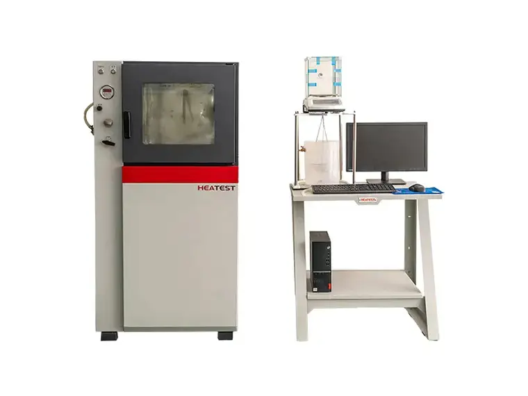
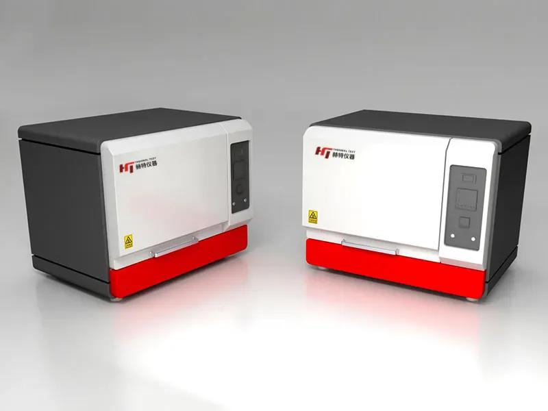
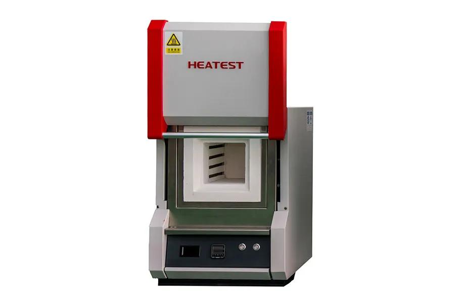
Selecting the right high temperature test gear is a decision that directly impacts product reliability, safety, and regulatory compliance. Whether you are evaluating material behavior under extreme heat or validating electronic components for aerospace applications, the equipment you choose must deliver consistent performance under demanding conditions. With countless options on the market, asking the right questions before making a purchase can save you from costly downtime and inaccurate test results. Below are the ten most critical questions every engineer and procurement professional should ask when evaluating high temperature test gear, with insights drawn from years of field experience and the engineering depth of HEATEST Instrument.

1. What Is the True Temperature Range and Uniformity?

Many manufacturers claim broad temperature ranges, but the real question is whether the system can maintain uniform conditions across the entire working volume. Uneven heating leads to skewed data and failed tests. Ask for documented uniformity data at multiple set points. HEATEST Instrument designs its chambers with advanced air distribution and multi-zone control to ensure ±0.5°C uniformity even at the upper end of the range. Verify that the published specifications match the conditions your tests require.

2. How Fast Can the System Ramp and Stabilize?

Thermal-shock-testing-machine

Ramp rate and stabilization time directly affect test throughput and energy consumption. A system that takes hours to reach 1000°C may not be suitable for accelerated life testing. Inquire about both heating and cooling rates, and whether the system can maintain stable temperature after rapid transitions. HEATEST Instrument uses high-performance heating elements and intelligent PID algorithms to achieve fast ramps without overshoot, reducing overall test cycle time.

3. What Is the Long-Term Reliability of the Heating Elements?

Heating elements are the heart of any high temp test gear. Premature failure causes downtime and expensive repairs. Ask about the element material, warranty, and typical lifespan under continuous operation. HEATEST Instrument sources industrial-grade Kanthal and silicon carbide elements that are proven in thousands of hours of field use. Additionally, their modular design allows quick replacement without dismantling the entire chamber.

For more detailed information on the top ten questions to ask when selecting high-temperature testing equipment, please click to visit: https://www.lyheatest.com/tester-knowledge/high-temp-test-gear/