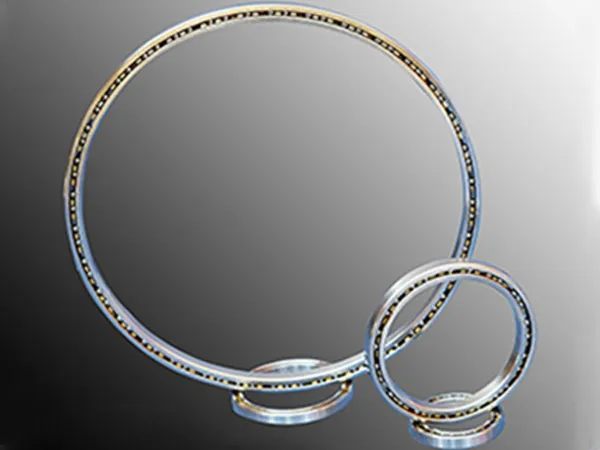
The load capacity of trailer turntable bearings can vary significantly based on the specific type, size, and design of the bearing, as well as the application’s operating conditions. Manufacturers typically provide a range of load capacities, often expressed as an axial load in kN (kilonewtons) or tons. For example, some models of turntable bearings are designed for axle loads ranging from 7.5 to 250 kN (approximately 0.76 to 25.5 metric tons).

Factors Influencing Load Capacity

trailer turntable bearings

Several factors affect the actual load capacity of a turntable bearing:

Bearing Type and Design:

Ball bearings: These are suitable for lighter loads and agricultural vehicles, offering smooth rotation.

Roller bearings: These are used for heavier-duty applications and offer a much higher load capacity and durability.

Double-row bearings: These are designed to provide both precision and strength, handling a combination of axial, radial, and moment loads.

Operating Speed: The load capacity is inversely related to speed. For example, a bearing’s load capacity may increase by up to 40% at speeds below 25 km/h compared to its rated capacity at higher speeds. Conversely, load capacity may decrease at speeds above 25 km/h.

trailer turntable bearings

Application and Usage:

Road conditions: The capacity is typically rated for paved, standard road conditions.

Trailer type: The load capacity can be influenced by the type of trailer, such as two-axle full trailers, which may allow for a 10% increase in the specified axial load.

Mounting and Lubrication: Proper installation and maintenance, including correct lubrication, are critical to achieving the rated load capacity and ensuring the bearing’s longevity.

More detailed information on the load capacity of trailer turntable bearings can be found at: https://www.mcslewingbearings.com/a/news/trailer-turntable-bearing-load-capacity.html

Trailer turntable bearings are crucial for the smooth and safe operation of trailers, especially those with steerable axles. When these bearings encounter issues, they can lead to significant problems.

Common Trailer Turntable Bearing Problems and Solutions

Trailer turntable bearings

1. Excessive Play or Looseness

Problem: This is often the most noticeable issue. You might hear clunking noises, feel excessive movement when turning, or see the trailer wheel assembly wobble.

It’s usually caused by wear in the bearing components, improper adjustment, or damaged mounting points.

Solution:

Inspection: First, safely jack up the trailer so the wheels are off the ground. Grip the wheel assembly firmly at 12 and 6 o’clock, then 3 and 9 o’clock, and try to rock it. Any significant movement indicates play.

Adjustment: Many turntable bearings have an adjustment mechanism (often a castellated nut and cotter pin). Consult your trailer’s manual for the correct torque specifications and adjustment procedure. Overtightening can damage the bearings, while undertightening leaves play.

Replacement: If adjustment doesn’t resolve the play, or if there’s visible damage to the bearing races or balls/rollers, replacement is necessary. This can be a complex job and might require specialized tools.

2. Roughness or Grinding Sensation

Problem: When you rotate the turntable by hand (with the trailer supported), you might feel a gritty, lumpy, or grinding sensation. This is a strong indicator of contaminated grease, damaged bearing components (pitting, spalling), or rust within the bearing.

Solution:

Lubrication: If the roughness is minor, sometimes a thorough cleaning and re-greasing with the correct type of high-quality grease can help.

Replacement: For significant roughness, especially if accompanied by noise, the bearings are likely damaged beyond repair and need to be replaced. Damaged bearing surfaces will continue to wear quickly.

For more detailed information on common problems and solutions for trailer turntable bearings, please click here:https://www.mcslewingbearings.com/a/news/common-trailer-turntable-bearing-problems-and-solutions.html

When planning an industrial, commercial, or agricultural construction project, understanding the steel structure factory price is one of the most important steps. Steel structures have become the preferred choice for modern buildings due to their durability, cost-effectiveness, fast installation, and design flexibility.However, the price of a steel structure factory can vary widely depending on several factors such as raw material costs, design complexity, production process, surface treatment, and installation requirements.

Steel Structure Factory Price Guide

Steel Structure Factory

The cost per square meter (or square foot) for a steel structure can vary widely, typically ranging from $250 to $800+ USD per square meter for the building shell, and potentially much higher when you include full fit-out, foundations, and specialized requirements. This wide range is due to several key factors:

Type of Steel Structure:

Light Steel Structure (e.g., small warehouses, workshops, agricultural buildings): These tend to be on the lower end, perhaps $250 – $450/sqm.

Medium Steel Structure (e.g., larger factories, multi-story industrial buildings, commercial complexes): These might fall in the $400 – $700/sqm range.

Heavy Steel Structure (e.g., high-rise buildings, large span bridges, complex industrial plants): These can easily exceed $700 – $1000+/sqm due to the engineering complexity, heavier sections, and specialized fabrication.

Material Costs:

Steel Price Fluctuations: The global price of steel is a major driver. Volatility in steel markets directly impacts the final cost.

Steel Grade: Different grades of steel (e.g., Q235, Q345) have different strengths and costs.

Section Type: Hot-rolled sections (I-beams, H-beams) are common, but cold-formed sections or built-up sections might be used depending on design, affecting cost.

Design and Engineering Complexity:

Span and Height: Larger spans and greater heights require more robust (and thus more expensive) steel members.

Architectural Complexity: Unique shapes, curves, or aesthetically driven designs add significant engineering and fabrication costs.

Load Requirements: Buildings in areas with heavy snow, high winds, or seismic activity require stronger designs, increasing material and fabrication costs.

Fabrication Costs:

Welding and Cutting: The amount and complexity of welding, cutting, and drilling required.

Surface Treatment:

Basic Primer: Least expensive.

Standard Paint (e.g., alkyd paint, epoxy primer + polyurethane topcoat): Adds cost for materials and labor.

Hot-dip Galvanizing: Provides superior corrosion resistance but is significantly more expensive than painting. This is often necessary for outdoor or corrosive environments.

Fireproofing: Intumescent paints or fire-resistant board systems add considerable cost but are crucial for safety in many building types.

Steel Structure Factory

Transportation Costs:

Distance from Factory: The further the project site is from the fabrication factory, the higher the shipping costs.

Logistics Complexity: Difficult access roads or urban delivery restrictions can increase costs.

More detailed information about steel structure factory prices can be found here: https://www.meichensteel.com/a/news/steel-structure-factory-price.html

Steel structure cold storage warehouses have become the industry standard for food, pharmaceuticals, and other temperature-sensitive goods. They combine strength, durability, and flexibility, making them ideal for both small and large-scale storage solutions.

How to Build a Steel Structure Cold Storage Warehouse

Steel structure cold storage warehouses

Why Choose Steel Structure for Cold Storage?

1.High Strength-to-Weight Ratio: Steel provides robust support with less material,reducing construction costs.

2.Durability: Resistant to termites, mold, and rot, ensuring a longer lifespan compared to traditional materials.

3. Design Flexibility: Can be customized for various sizes, insulation types, and layouts, meeting diverse storage needs.

4. Faster Construction: Prefabricated steel components allow quicker assembly on-site.

5. Energy Efficiency: Well-insulated steel structures maintain consistent temperatures,reducing refrigeration costs.

Key Components of a Steel Structure Cold Storage Warehouse

Steel Frame: Main skeleton providing structural support.

Insulated Panels:Sandwich panels with polyurethane or polystyrene cores for optimal thermal efficiency.

Flooring: Reinforced concrete or steel panels with anti-slip coating.

Doors & Loading Bays: Insulated, airtight doors with fast-acting options for minimal temperature loss.

Refrigeration System: High-efficiency cooling units tailored to warehouse size and stored goods.

Step-by-Step Build Process

1. Planning and Design:

Needs Assessment: Determine the size, capacity, temperature requirements, and specific usage of the cold storage. What kind of products will be stored? What are the desired temperature ranges?

Site Selection: Choose a location with good access, proper drainage, and sufficient space for the warehouse and any future expansion.

Regulatory Compliance: Research and comply with all local building codes, zoning regulations, and environmental standards.

Architectural and Structural Design: Engage architects and structural engineers to design the building. This includes detailed plans for the steel frame, insulation, refrigeration system, flooring, roofing, and utility connections.

Refrigeration System Design: A specialized refrigeration engineer will design the cooling system, considering factors like ambient temperature, insulation R-value, product heat load, and desired internal temperature. This will include selecting compressors, evaporators, condensers, and controls.

2. Foundation and Site Preparation:

Site Clearance and Grading: Prepare the site by clearing vegetation, leveling the ground, and ensuring proper drainage.

Excavation: Dig trenches and pits for the foundation according to the design plans.

Foundation Construction: Pour concrete foundations, which might include spread footings, strip footings, or a slab-on-grade. For cold storage, it’s crucial to consider frost heave prevention, which often involves heated sub-slabs or insulation under the floor to prevent the ground beneath from freezing and expanding.

More details about how to build a steel structure cold storage can be found here: https://www.meichensteel.com/a/news/how-to-build-a-steel-structure-cold-storage-warehouse.html

The terms “light steel structure” and “heavy steel structure” generally refer to the scale and application of steel in construction.

The differences between light and heavy steel structures are primarily based on the material thickness, load-bearing capacity, and typical applications. These factors determine a project’s cost, construction timeline, and overall durability.

Difference Between Light Steel Structure and Heavy Steel Structure

Steel Structure

Light Steel Structure

Light steel structures typically use thin-gauge steel members, often cold-formed, which means the steel is shaped at room temperature.

Material Thickness: Generally, the steel sections are thin, ranging from about 1mm to 3mm (0.04 to 0.12 inches).

Manufacturing Process: Cold-formed steel (CFS) is common. This involves bending and shaping thin steel sheets into various profiles (like C-channels, Z-sections, or hat sections) without heating.

Weight: Lighter in weight compared to heavy steel structures, which contributes to easier handling and reduced foundation costs.

Strength-to-Weight Ratio: Offers a high strength-to-weight ratio, making it efficient for certain applications.

Applications:

Residential Buildings: Often used for framing in single-family homes, multi-story apartments (up to a certain height).

Commercial Buildings: Suitable for low-rise commercial structures, office partitions, interior walls, roof trusses, and flooring systems.

Non-Load Bearing Walls: Excellent for interior partition walls and curtain wall systems.

Modular Construction: Frequently employed in prefabricated and modular building components.

Roof Trusses: Commonly used for creating lightweight roof support systems.

Construction Speed: Faster erection due to prefabrication and lighter components.

Cost: Generally more cost-effective for smaller to medium-sized projects.

Fire Resistance: May require additional fire protection measures due to the thinner gauge steel.

Steel Structure

Heavy Steel Structure

Heavy steel structures use thicker and heavier hot-rolled steel sections, designed for significant load-bearing capacity.

Material Thickness: Steel sections are much thicker, often ranging from 6mm (0.24 inches) upwards, with I-beams, H-beams, and large plate girders being common.

For more detailed information on the difference between light steel structure and heavy steel structure, please click here: https://www.meichensteel.com/a/news/difference-between-light-steel-structure-and-heavy-steel-structure.html

Steel and concrete are the two most common materials for large-scale construction, but they have key differences in properties, construction methods, cost, and environmental impact. Generally, steel structures are known for their high strength-to-weight ratio, which allows for lighter, more flexible designs and faster construction, while concrete structures are valued for their high compressive strength, durability, and fire resistance.

Differences Between Steel Structure and Concrete Structure

steel structures

Steel Structure

Description: Steel structures are made from interconnected steel components, such as beams, columns, and trusses, which are fabricated in a workshop and then assembled on-site using bolts or welding.

Advantages:

High Strength-to-Weight Ratio: Steel is incredibly strong for its weight, allowing for lighter structures and longer spans without intermediate supports.

Speed of Construction: Fabrication off-site and quick assembly on-site significantly reduce construction time.

Durability: Steel is a durable material, resistant to rot, insects, and aging.

Flexibility and Adaptability: Steel structures can be easily modified, expanded, or even disassembled and reused.

Seismic Resistance: Steel’s ductility allows it to deform under stress without brittle failure, making it good for earthquake-prone areas.

Sustainability: Steel is 100% recyclable, making it an environmentally friendly option.

Disadvantages:

Corrosion: Steel is susceptible to rust when exposed to moisture and oxygen, requiring protective coatings or regular maintenance.

Fire Resistance: While steel doesn’t burn, its strength can significantly decrease at high temperatures, leading to structural collapse. Fireproofing measures are essential.

Cost: The initial cost of steel materials and fabrication can be higher than concrete.

Fatigue: Under repeated cyclic loading, steel can experience fatigue failure.

Typical Applications: High-rise buildings, bridges, industrial buildings, stadiums, long-span roofs, and aesthetically exposed structures.

Concrete Structure

More detailed information about the difference between steel structure and concrete structure can be found here: https://www.meichensteel.com/a/news/differences-between-steel-structure-and-concrete-structure.html

In shipbuilding,welding rotators are essential for handling heavy cylindrical and round components, improving weld quality, speeding up production, and ensuring worker safety.They are especially valuable for large-scale ship structures where precision and efficiency are critical.

Welding rotators play a crucial role in the shipbuilding industry, significantly improving the efficiency, quality, and safety of welding large cylindrical or asymmetrical components.

Welding Rotator in the Shipbuilding Industry Functions

welding rotators

Positioning and Rotation: The most fundamental function is to accurately position and rotate heavy, often irregularly shaped, sections of a ship during the welding process. This ensures that welds can be performed in the optimal “downhand” position, which is the easiest and most efficient for welders, leading to better weld quality and faster completion times.

Handling Large and Heavy Components: Ship components like hull sections, storage tanks, pressure vessels, and large pipes can be incredibly heavy and cumbersome. Welding rotators, especially those with robust power and idler sections, are designed to safely support and maneuver these massive structures, eliminating the need for complex and often dangerous crane operations for repositioning during welding.

Improved Weld Quality: By providing stable and controlled rotation, rotators enable welders to maintain a consistent torch angle, travel speed, and arc length. This consistency is vital for producing high-quality, uniform welds with fewer defects, which is critical for the structural integrity and longevity of a ship.

Increased Welding Speed and Efficiency: Downhand welding is significantly faster than welding in other positions (horizontal, vertical, overhead). By continuously presenting the weld joint in the downhand position, rotators dramatically increase welding speed and reduce the overall time required for fabrication. This translates to higher productivity and cost savings.

welding rotators

Enhanced Welder Safety and Comfort: Operating large ship components can be hazardous. Rotators reduce the physical strain on welders by minimizing the need for awkward postures or reaching. They also create a safer working environment by keeping the heavy workpiece securely held and rotating it smoothly, reducing the risk of accidents associated with manual manipulation or unstable positioning.

More detailed information about the role of welding rotator in the shipbuilding industry can be found at: https://www.bota-weld.com/en/a/news/welding-rotator-in-the-shipbuilding-industry-functions.html

Welding rotators are essential tools in the fabrication of pressure vessels, tanks, pipes, and other cylindrical workpieces. They are designed to rotate heavy components during the welding process, ensuring smooth operation, uniform weld seams, and higher efficiency. While there are different types of welding rotators, the two most commonly compared are self-aligning welding rotators and conventional welding rotators.

The main difference lies in their wheel adjustment mechanism and adaptability to different workpiece diameters:

Difference Between Self-aligning and Conventional Welding Rotator

Welding rotators

1. Self-Aligning Welding Rotator

Mechanism: Self-aligning rotators are designed with a unique mechanism where the rollers automatically adjust to the diameter of the workpiece. This is typically achieved through a system of pivoted arms or a walking beam design that allows the rollers to move closer together or further apart as needed.

Key Features:

Automatic Diameter Adjustment: This is the most significant feature. Once the workpiece is loaded, the rollers adjust themselves to securely cradle it.

Versatility: They can handle a wide range of workpiece diameters without manual adjustment of the roller spacing.

Ease of Use: Reduces setup time and operator effort, especially when frequently changing workpieces of different sizes.

Even Weight Distribution: The self-aligning mechanism often ensures a more even distribution of the workpiece weight across the rollers.

Higher Initial Cost: Generally more expensive due to the more complex mechanical design.

Best Suited For:

Workshops handling various diameters of cylindrical workpieces (e.g., pipes, tanks, pressure vessels).

Production lines where frequent changes in workpiece size are common.

Applications requiring quick setup and minimal manual intervention.

Automated welding processes where consistent rotation is crucial.

Welding rotators

2. Conventional (Adjustable) Welding Rotator

Mechanism: Conventional rotators require manual adjustment of the roller spacing to accommodate different workpiece diameters. This typically involves moving the roller carriages along a frame and securing them in place.

More detailed information about difference between self-aligning and conventional welding rotator can be found at: https://www.bota-weld.com/en/a/news/difference-between-self-aligning-and-conventional-welding-rotator.html

Offshore wind towers are critical components of modern renewable energy infrastructure, providing the foundation for wind towers installed in marine environments. Their manufacturing process is highly specialized, requiring high-quality wind tower welding production line,precision engineering, advanced welding techniques, and strict quality control to ensure long-term performance in harsh offshore conditions. From steel plate rolling and section welding to surface treatment and final assembly, each stage of production is designed to deliver structural stability, corrosion resistance, and the ability to withstand extreme wind and wave loads. Understanding the manufacturing process of offshore wind towers helps highlight the complexity, technological innovation, and stringent standards behind the development of these essential structures in the global transition to clean energy.

Offshore Wind Towers Manufacturing Process

wind tower welding production line

1. Material Sourcing and Preparation:

The primary material for wind towers is high-strength steel. Large steel plates, often several meters wide and thick, are sourced from specialized steel mills. These plates undergo initial inspection for defects and are then cut to the required dimensions using laser or plasma cutting machines.

2. Plate Rolling:

The flat steel plates are then rolled into cylindrical or conical sections. This is achieved using large rolling machines that gradually bend the steel into the desired curvature. The rolling process requires precision to ensure the correct diameter and seamless fit for subsequent sections.

3. Longitudinal Welding:

Once rolled, the edges of each steel section are welded together to form a complete cylinder. This is typically done using automated submerged arc welding (SAW) or gas metal arc welding (GMAW) processes, which provide strong and consistent welds. Multiple weld passes may be required due to the thickness of the steel.

4. Section Assembly (Can Assembly):

Several individual cylindrical or conical sections are then assembled to form larger tower sections, often called “cans.” This involves fitting the ends of the rolled and welded sections together and performing circumferential welds. Again, automated welding techniques are commonly used to ensure high-quality, continuous welds.

5. Flange Welding:

Flanges, which are large, thick steel rings, are welded to the ends of each tower section. These flanges are critical for connecting the tower sections together at the installation site using high-strength bolts. The welding of flanges requires extreme precision to ensure perfect alignment.

6. Internal Components and Access:

More detailed information about the manufacturing process of offshore wind towers can be found here: https://www.bota-weld.com/en/a/news/offshore-wind-towers-manufacturing-process.html

Customizing a wind tower welding production line involves a comprehensive assessment of your specific manufacturing needs and then selecting and integrating the appropriate automated machinery to meet those requirements. This process is highly specialized and requires a tailored approach rather than a one-size-fits-all solution.

Customized Wind Tower Welding Production Line

Wind Tower Welding Production Line

1. Key Factors for Customization

To effectively customize a production line, you must first define your operational goals and constraints. These factors will dictate the design and equipment of your line.

Production Capacity: Determine the number of tower sections or entire towers you need to produce per week, month, or year. This directly influences the required welding speed, material handling capacity, and the overall level of automation.

Tower Specifications: The dimensions and materials of the towers you will produce are critical.

Diameter and Thickness: The range of diameters and steel plate thicknesses you plan to use will determine the size and power of key equipment like plate rolling machines and welding power sources.

Section Length: The standard length of your tower “cans” dictates the required length of welding manipulators and the overall workshop layout.

Material Grade: Different steel grades have unique welding requirements that will influence the choice of welding processes and consumables.

Workshop Layout: The physical space of your facility is a major constraint.

Available Space: Map out your facility to account for the entire production flow, from raw material storage to finished product handling.

Ceiling Height and Crane Capacity: Ensure your overhead cranes can handle the largest and heaviest tower sections.

Material Flow: Design a logical, linear flow to minimize unnecessary handling and movement.

2. Key Customization Areas

Material Handling Systems:

Automated Loading/Unloading: Implement robotic or gantry systems for efficient movement of tower sections.

Conveyors and Rollers: Customize the size and type of conveyors to handle the dimensions and weight of your specific tower sections.

Positioners and Rotators: Utilize heavy-duty positioners and rotators to allow for optimal welding angles and access.

Fit-Up Stations: Design specialized fit-up stations that ensure precise alignment of tower sections before welding.

Welding Process Optimization:

Welding Method Selection: Choose the most suitable welding processes for wind tower fabrication (e.g., submerged arc welding (SAW), gas metal arc welding (GMAW), flux-cored arc welding (FCAW)).

Automated Welding Carriages: Integrate automated welding carriages that can traverse the tower sections, maintaining consistent speed and arc length.

Multi-Wire Welding: Consider multi-wire SAW systems for increased deposition rates and faster welding.

Narrow Gap Welding: Implement narrow gap welding techniques to reduce weld volume and improve efficiency.

Robotic Welding Cells: For specific, repetitive tasks or complex geometries, robotic welding can offer high precision and repeatability.

Quality Control and Inspection:

Non-Destructive Testing (NDT): Integrate automated NDT systems (e.g., ultrasonic testing, eddy current testing) directly into the production line to ensure weld integrity.

Vision Systems: Implement vision systems for real-time weld monitoring, defect detection, and precise seam tracking.

Data Logging and Traceability: Establish systems to record welding parameters and inspection results for comprehensive traceability.

Automation and Control Systems:

PLC/HMI Control: Implement a centralized PLC (Programmable Logic Controller) and HMI (Human-Machine Interface) for comprehensive control and monitoring of the entire line.

For more detailed information on how to customize the wind turbine tower welding production line, please click here: https://www.bota-weld.com/en/a/news/customized-wind-tower-welding-production-line.html