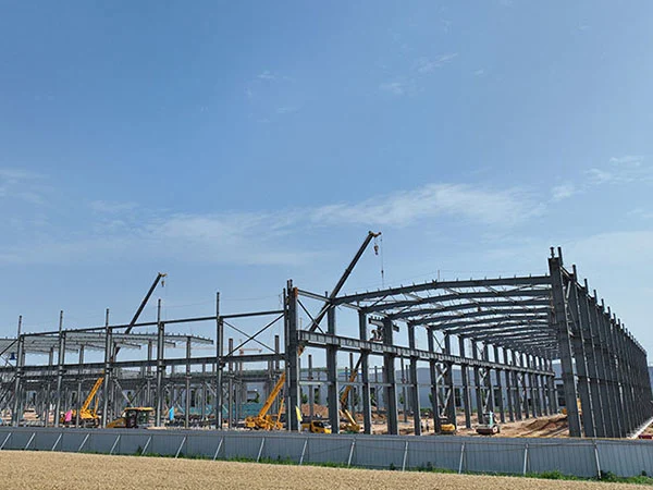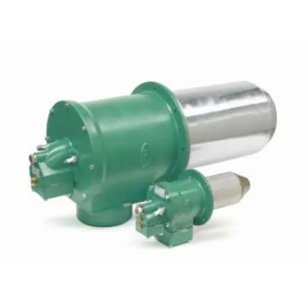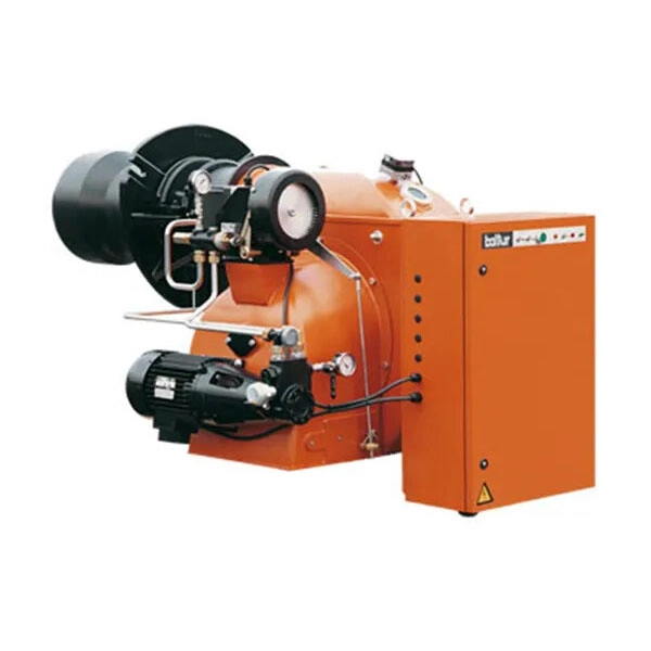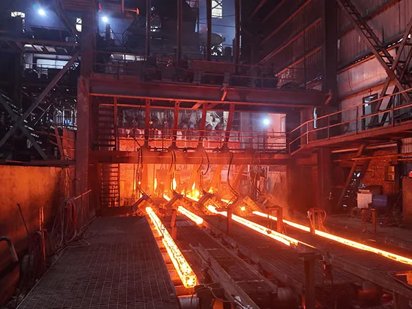
Designing a steel structure warehouse is not simply a matter of choosing the right steel sections and creating a large enclosed space. For experienced buyers, a successful warehouse project should balance structural safety, construction efficiency, long-term performance, and overall project cost.

From the initial design stage to fabrication, transportation, and installation, every decision can have a direct impact on the final result. Here are eight key factors that buyers should consider when planning a steel structure warehouse.

1. Understand the Warehouse’s Actual Requirements

Before starting the structural design, it is important to clearly define how the warehouse will be used.

The building’s purpose, storage system, material handling equipment, internal traffic, loading requirements, and future expansion plans can all influence the structural design.

For example, a warehouse equipped with overhead cranes may require a different structural system from a standard storage warehouse. Similarly, high-rack storage may require greater clear height and careful consideration of column spacing.

A well-designed warehouse starts with a clear understanding of its operational requirements.

2. Choose the Right Structural System

The structural system should be selected according to the building’s span, height, location, loads, and intended use.

Common steel structure warehouse systems include portal frames, rigid frames, and other customized structural solutions. The goal is not simply to use more steel, but to achieve an appropriate balance between structural performance and material efficiency.

An experienced steel structure supplier can optimize the frame layout, member sizes, and connection design according to the project’s specific requirements.

3. Consider Local Design Loads and Site Conditions

A warehouse may be exposed to different environmental loads depending on its location.

Important factors include:

  • Wind loads
  • Seismic loads
  • Snow loads, where applicable
  • Rainfall and drainage requirements
  • Temperature and environmental conditions
  • Soil and foundation conditions

Using the correct local design parameters at the beginning can help avoid costly structural modifications later.

4. Optimize Column Spacing and Building Dimensions

Column spacing, building width, roof height, and bay layout have a significant influence on both the building’s functionality and steel consumption.

A wider span may provide better internal flexibility, while an optimized bay spacing can reduce unnecessary steel usage and simplify fabrication.

…

Click here for more details on designing efficient steel-structure warehouses—8 key factors that experienced buyers should know: https://www.hcggsteel.com/a/news/how-to-design-an-efficient-steel-structure-warehouse:-8-key-factors-experienced-buyers-should-know.html
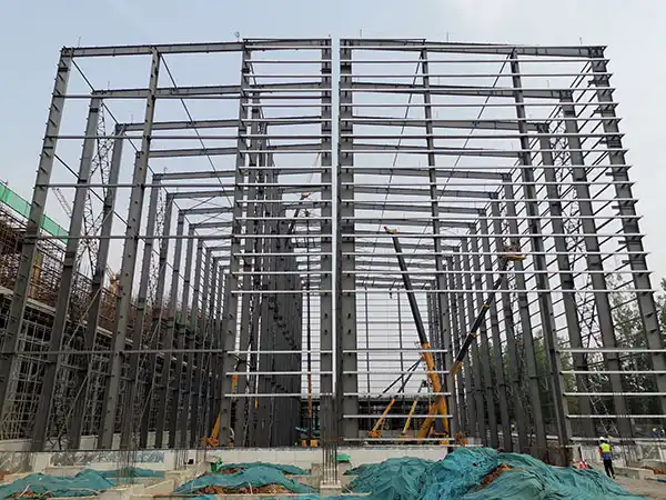

The question of how tall a steel structure factory can safely be is not one with a single numerical answer. It depends on a complex interplay of engineering principles, local building codes, site conditions, and intended use. For potential investors and facility planners, understanding these boundaries is critical to avoiding costly overruns or structural risks. This article breaks down the core factors that determine the maximum safe height for a steel structure factory, and how industry leaders like HCGG apply rigorous standards to push these limits responsibly.

What Limits the Height of a Steel Structure Factory?

Unlike residential towers, industrial factories must balance vertical space with heavy equipment loads, crane operations, and large open spans. The primary constraints are structural stability, lateral load resistance, and foundation capacity. While a single-story steel building can theoretically reach heights of 30 meters or more, practical safety limits are governed by:

  • Wind loads – Taller buildings experience higher wind pressures, requiring stronger bracing and thicker columns.
  • Seismic forces – In earthquake-prone regions, height increases sway demands and ductility requirements.
  • Column slenderness – Steel columns must be designed to avoid buckling under combined axial and bending stresses.
  • Roof and wall stability – Long-span roofs (common in factories) become more flexible as height increases.

Typical Height Ranges for Steel Factories

Most industrial steel buildings fall between 6 meters (20 ft) and 18 meters (60 ft) in eave height. Specialized facilities like aircraft hangars or high-bay warehouses can reach 30 meters (100 ft) or more, but require premium-grade steel sections and advanced connection detailing. HCGG has delivered multiple projects where eave heights exceed 25 meters, always with site-specific wind and seismic analysis.

Key Engineering Factors That Determine Safe Height

To answer “how tall can it safely be,” engineers evaluate three critical systems: the primary framing (columns and rafters), the secondary framing (purlins, girts), and the foundation. Each plays a role in the overall height capability.

1. Wind Load and Drift Control

Wind load increases with the square of height. For a factory with an eave height of 12 meters, wind pressure may be moderate; at 30 meters, it can triple. Engineers must design moment-resisting frames, cross-bracing, or shear walls to keep lateral drift below acceptable limits (typically H/200 to H/400). HCGG uses computational fluid dynamics (CFD) simulations to optimize frame spacing for tall structures, reducing steel tonnage while maintaining safety.

…

For more detailed information on the maximum safe height for steel structure factories, please click here: https://www.hcggsteel.com/a/news/steel-structure-height.html

The decision to purchase a used steel factory building often arises from a need for speed and budget efficiency. Whether you are expanding an existing operation or establishing a new manufacturing facility, a pre-owned structure can offer significant advantages in terms of cost and timeline. However, unlike a new build, a used steel building comes with its own set of variables—from hidden wear and tear to outdated compliance records. This article provides a balanced examination of the pros and cons, drawing on industry expertise from HCGG, a company with over a decade of experience in sourcing and reconditioning used steel factory buildings for industrial clients.

Understanding the Appeal of Used Steel Factory Buildings

The primary drivers for choosing a pre-owned steel building are financial and logistical. When the immediate need for a functional workspace outweighs the desire for a custom-designed facility, a used structure becomes a compelling alternative.

Cost Savings

The most obvious benefit is the lower upfront cost. A used steel building typically sells for 30% to 50% less than the price of a comparable new structure. This reduction includes not only the steel frame and cladding but often the foundation components (if reusable) and ancillary systems like overhead cranes or insulation. For companies with tight capital budgets, this price difference can free up funds for equipment or working capital.

Immediate Availability

New construction projects can take six to twelve months from permit to completion. A used building that has already been dismantled and inspected can be delivered within weeks. This speed-to-market is critical for businesses that need to start production quickly or secure a location before a lease expires.

Proven Structural Performance

A steel building that has stood for 15 or 20 years has already proven its ability to withstand local weather conditions, snow loads, and wind forces. In many cases, the existing structure has been maintained and modified to meet industry standards, giving buyers a tangible track record rather than theoretical engineering calculations.

The Potential Drawbacks of a Pre-Owned Structure

Despite the advantages, purchasing a used steel factory building requires careful scrutiny. The risks are often hidden behind the initial price tag.

Hidden Structural Issues

Corrosion is the most common enemy of older steel buildings. Even if the exterior appears sound, moisture may have damaged the base plates, gusset plates, or roof purlins. Additionally, welding repairs from previous modifications can create stress risers. A professional inspection by a licensed structural engineer is not optional—it is essential. Buyers should budget for potential reinforcement costs that can add 10% to 15% to the initial purchase price.

…

Click here for detailed information and an analysis of the pros and cons of purchasing a used steel-structure factory building: https://www.hcggsteel.com/a/news/used-steel-factory-buying-guide.html

Choosing the right structural system for a new factory is a decision that impacts budget, construction timeline, operational efficiency, and long-term maintenance. Two dominant options in industrial construction are steel structures and precast concrete systems. Each offers distinct advantages depending on the factory’s size, load requirements, expansion plans, and environmental conditions. This article provides an objective, data-driven comparison of steel structure versus precast concrete for factories, helping facility owners and project managers make an informed choice. HCGG draws on extensive experience in both systems to guide clients toward the optimal solution.

1. Structural Strength and Design Flexibility

Steel structure advantages

Steel frames provide excellent strength-to-weight ratios, allowing for large clear spans of 30–50 meters without intermediate columns. This is ideal for manufacturing floors that require unobstructed space for machinery, assembly lines, or storage racking. Steel components can be prefabricated off-site to tight tolerances, and the modular nature allows easy future expansion – a critical factor for growing operations. Additionally, steel supports mezzanine levels, overhead cranes, and heavy equipment attachments with simpler connection details.

Precast concrete advantages

Precast concrete offers inherent compressive strength and fire resistance. Factory buildings with heavy floor loads – such as those storing raw materials or finished products on multiple levels – benefit from concrete’s load-bearing capacity. Precast components are cast in controlled environments, ensuring consistent quality and durability. However, column spacing is typically limited to 6–12 meters due to the weight of pre-stressed beams, which can restrict layout flexibility for certain production lines.

  • Steel: maximum clear spans, flexibility for future reconfiguration, easier to add openings or extensions.
  • Precast Concrete: superior for heavy vertical loads, better vibration damping for sensitive equipment, inherent fire rating without additional coating.

2. Construction Speed and Site Impact

Time-to-production is often the primary driver for factory owners. Steel structures typically erect faster than precast concrete because steel members are lighter, connections use bolting or welding, and erection can proceed in parallel with foundation work. A steel-framed factory can be enclosed within 4–6 weeks after foundation completion, depending on size. Precast concrete requires longer curing time for connections and often needs heavy cranes for panel placement, extending the erection schedule to 8–12 weeks or more. However, precast eliminates the need for additional fireproofing or cladding in many cases, potentially offsetting some time.

HCGG recommends a detailed schedule analysis based on local labor availability, crane capacity, and permit requirements. For projects with aggressive timelines, steel often wins; for those where noise or dust on-site must be minimized, precast’s off-site fabrication reduces site disturbance.

3. Cost Comparison: Initial Investment vs. Lifecycle Cost

Initial construction cost

Steel structures generally have lower initial costs than precast concrete for single-story factories with moderate loads. The price difference ranges from 5–15% in favor of steel, depending on steel market prices. Precast concrete requires more expensive formwork and heavier foundations due to the dead load of concrete elements. However, for facilities requiring high fire resistance or located in high seismic zones, precast may require less additional bracing or fireproofing, narrowing the gap.

…

For more detailed information comparing factory steel structures and precast concrete structures, please click here: https://www.hcggsteel.com/a/news/steel-vs-precast-factory.html

Maintaining precise temperature control within steel manufacturing facilities is not merely a matter of operational comfort; it is a critical factor that directly impacts product quality, energy efficiency, and equipment longevity. The extreme heat generated during processes such as casting, rolling, and heat treatment demands robust insulation strategies to minimize thermal loss, protect personnel, and ensure consistent production parameters. Choosing the right insulation option from the myriad of available materials and systems can be daunting. This article provides a rigorous, decision-focused comparison of the leading insulation solutions for steel factories, offering the technical clarity needed to select the most cost-effective and durable approach for specific plant areas.

Core Insulation Materials for Steel Plant Applications

In the harsh environment of a steel mill, insulation must withstand high temperatures, mechanical abrasion, moisture, and chemical exposure. The most common materials fall into several categories, each with distinct performance characteristics.

Ceramic Fiber

Ceramic fiber blankets, modules, and boards are widely used due to their low thermal conductivity, light weight, and ability to handle continuous temperatures up to 1260°C (2300°F). They are ideal for lining furnaces, ladles, and reheating zones where rapid thermal cycling occurs. However, they are susceptible to shrinkage at very high temperatures and can degrade in the presence of molten metal splash.

Mineral Wool (Rock Wool / Slag Wool)

Mineral wool offers a cost-effective solution for moderate temperature applications (up to 1000°C / 1832°F). It provides good acoustic damping and fire resistance. Its dense structure resists vibration better than ceramic fiber, making it suitable for piping, ducts, and structural steel protection. Under prolonged moisture exposure, however, its insulation value drops significantly.

Calcium Silicate

Calcium silicate blocks and boards are known for their structural strength and ability to resist water absorption compared to mineral wool. They are often used in high-temperature steam lines and equipment operating below 1000°C. Their rigidity makes installation easier on flat surfaces, but they are heavier and more brittle than fiber-based products.

Refractory Castables and Brick

For the most extreme conditions—direct contact with molten metal or slag—dense refractory materials are required. Alumina-based castables, firebrick, and silicon carbide products provide unmatched wear resistance and heat storage capacity. They are typically used in furnace hearths, tundishes, and hot metal transfer systems. The trade-off is higher material cost, labor-intensive installation, and longer heating/cooling cycles.

Key Performance Comparison: What Matters Most for Steel Factory Operations

To make an informed decision, potential buyers must evaluate insulation options across several critical dimensions. The table below summarizes the essential differences, but we will expand on each below. Note: HCGG recommends selecting materials based on the specific temperature zone and mechanical exposure, rather than a one-size-fits-all approach.

  • Thermal Efficiency: Ceramic fiber offers the lowest thermal conductivity (0.05–0.15 W/m·K at moderate temperatures), allowing thinner layers to achieve similar performance compared to mineral wool (0.04–0.10 W/m·K) or calcium silicate (0.06–0.15 W/m·K). For highest temperature zones (above 1200°C), only refractories can withstand the heat, though they conduct more heat (1.0–2.5 W/m·K), requiring greater thickness.

…

Click here for more detailed information on thermal insulation solutions for temperature control in steel plants: https://www.hcggsteel.com/a/news/steel-insulation-guide.html

Replacing an industrial burner is not a simple plug-and-play task. Every furnace has a unique combustion chamber geometry, heat transfer requirement, and draft characteristic. A mismatched burner can lead to poor efficiency, flame instability, increased emissions, or even equipment damage. Understanding the critical specifications that govern burner-to-furnace compatibility is essential for a successful retrofit. This guide walks through the key parameters you must evaluate, with practical insights to help you select a burner that delivers optimal performance and longevity.

Understanding the Critical Specifications for Burner Replacement

Before you start comparing burner models, you need a clear picture of your furnace’s operating envelope. The most important specs fall into three categories: thermal output, flame geometry, and air/fuel delivery.

Firing Rate (BTU/hr) and Turndown Ratio

The firing rate is the burner’s maximum heat input, typically measured in BTU per hour. Your replacement burner must meet or slightly exceed the furnace’s design heat demand. But just as important is the turndown ratio — the ratio of maximum to minimum firing rate. A high turndown ratio (e.g., 10:1) allows the burner to modulate output during low-load periods, reducing cycling losses and improving overall efficiency. For processes with variable heat demand, a burner with at least 8:1 turndown is recommended. Always verify that the burner’s minimum firing rate stays above the furnace’s stable combustion threshold to avoid flameout or excessive CO formation.

Flame Shape and Length

The flame must fit the furnace’s combustion zone without impinging on walls or tubes. Key measurements include flame length (distance from burner nozzle to flame tip) and flame diameter. For example, a long, narrow flame is suitable for cylindrical furnaces, while a short, wide flame works better in rectangular chambers. Many burner manufacturers, including SHUXIN, offer adjustable flame nozzles or swirl vanes to fine-tune the shape. If you cannot find exact data, consult the burner supplier with your furnace drawings — a 3D CAD model of the combustion chamber will yield the most accurate recommendation.

Matching Burner Type to Furnace Design

Not all burners are built the same. The fundamental design — forced draft, natural draft, or something in between — must align with your furnace’s pressure profile and exhaust system.

Forced Draft vs. Natural Draft Burners

A forced draft burner uses a fan to push combustion air into the burner, creating positive pressure inside the furnace. This type is ideal for high-heat-density applications and furnaces with tall stacks or long duct runs. Natural draft burners rely on the chimney’s draft to draw air in, which is simpler but sensitive to stack temperature and wind conditions. If your existing furnace has a natural draft design, replacing it with a forced draft burner often requires upgrading the stack and controls. Conversely, converting a forced draft system to natural draft may reduce costs but limit turndown. SHUXIN offers both configurations and can provide a detailed pressure drop analysis to ensure compatibility.

Direct-Fired vs. Indirect-Fired Systems

In a direct-fired burner, combustion products mix directly with the process air. This is common for drying or heating applications where contamination is not critical. Indirect-fired burners use a heat exchanger to isolate combustion gases from the process stream, required for food, pharmaceutical, or clean-room environments. When replacing a burner, check the original system’s classification — swapping between direct and indirect often necessitates redesigning the heat exchanger or ducting, which adds cost and lead time.

…

For more information on industrial burner replacement: click here for details on key specifications that match your furnace design:https://www.sxburner.com/a/news/burner-replacement-guide.html

Cold start issues in large industrial burners present a persistent challenge for operators, often leading to delayed ignition, incomplete combustion, increased emissions, and accelerated equipment wear. When a burner is started from ambient temperature, the fuel-air mixture may fail to reach autoignition conditions, resulting in misfires or hazardous accumulation of unburned fuel. Addressing these problems requires a systematic approach to preheating — a set of strategies designed to raise the temperature of combustion air, fuel, and burner components before ignition. This article explores the root causes of cold start difficulties and presents proven preheating methods, with a focus on practical implementations that enhance reliability, safety, and efficiency. As an experienced provider of combustion solutions, SHUXIN has developed integrated preheating systems that help industrial facilities overcome these challenges while maintaining operational flexibility.

Understanding the Root Causes of Cold Start Failure

Cold start problems stem from the fundamental thermodynamics of combustion. At low temperatures, fuel vaporization slows down, the air-fuel mixture becomes less homogeneous, and the flame propagation speed decreases. For large industrial burners, these effects are magnified due to the high thermal mass of the combustion chamber and the long fuel supply lines. Common failure modes include:

  • Flame instability: The flame may extinguish shortly after ignition if the heat release rate is insufficient to sustain combustion.
  • Smoking and soot formation: Incomplete combustion at low temperature produces carbon particles that foul heat exchanger surfaces.
  • Thermal shock: Rapid introduction of hot flame into a cold burner body can cause differential expansion, cracking refractory linings.

Without proper preheating, operators often resort to prolonged purge cycles or multiple ignition attempts, which waste fuel and time. Therefore, a structured preheating strategy is not merely an optimization — it is a prerequisite for safe and reliable burner operation.

Preheating Strategies: From Simple to Advanced

Depending on burner design, fuel type, and operating requirements, preheating can be implemented at various points in the system. The following sections describe the most effective approaches.

1. Combustion Air Preheating

Raising the temperature of the incoming combustion air is one of the most direct methods to improve cold start performance. By using a heat exchanger that recovers waste heat from the flue gas, or integrating an electric or steam air heater, the air temperature can be elevated to 150–300 °C before mixing with fuel. This significantly lowers the activation energy required for ignition. SHUXIN’s air preheaters are designed with high-efficiency finned tubes that minimize pressure drop while maximizing heat transfer, ensuring stable air temperatures even during variable load conditions.

…

Click here for more details on preheating strategies to address cold-start issues in large industrial burners: https://www.sxburner.com/a/news/cold-start-preheating.html

When evaluating industrial burners, two ratings frequently dominate technical specifications: Annual Fuel Utilization Efficiency (AFUE) and turndown ratio. Understanding what these numbers mean is essential for selecting a burner that not only meets your process heat requirements but also minimizes fuel consumption and operational costs. For engineers, plant managers, and procurement professionals, AFUE and turndown ratio are not just abstract metrics—they directly influence energy bills, system reliability, and environmental compliance. This article explains both ratings in detail, explores their practical implications, and provides guidance on how to use them when selecting an industrial burner, with insights from industry specialist SHUXIN.

What Is AFUE and Why Does It Matter for Industrial Burners?

AFUE measures the percentage of fuel energy converted into usable heat over a typical heating season. In the industrial context, AFUE is calculated under standardized conditions and accounts for steady-state efficiency plus part-load losses. A burner with 85% AFUE means 85% of the fuel’s energy becomes heat; the remaining 15% escapes through flue gases, radiation, or other losses.

How AFUE Is Determined

Testing protocols vary by region, but generally AFUE considers:

  • Combustion efficiency – the completeness of fuel burning
  • Stack losses – heat carried away by exhaust gases
  • Standby losses – heat lost when the burner is idle

High AFUE burners typically incorporate advanced heat exchangers, precise air-fuel ratio controls, and low-excess-air operation. However, AFUE alone does not tell the whole story—especially for industrial applications where the burner operates at varying loads.

Turndown Ratio: The Key to Flexible, Efficient Operation

Turndown ratio (TDR) is the ratio between a burner’s maximum firing rate and its minimum stable firing rate. For example, a 10:1 turndown ratio means the burner can reduce its output to 10% of maximum capacity while maintaining stable combustion and acceptable efficiency.

Why High Turndown Matters

Industrial processes rarely run at constant heat demand. Batch operations, seasonal changes, and production line variations require the burner to modulate. A higher turndown ratio offers several advantages:

  • Energy savings – avoids wasteful on/off cycling; the burner matches load precisely
  • Reduced thermal stress – fewer cycles prolong equipment life
  • Better temperature control – minimizes overshoot and undershoot
  • Lower emissions – stable flame at low fire improves NOx and CO control

…

Click here for more detailed information on industrial burner efficiency ratings, specifically the meanings of AFUE and turndown ratio: https://www.sxburner.com/a/news/burner-efficiency-guide.html

For industries generating large volumes of used lubricants—from automotive service centers to manufacturing plants—disposal costs and environmental regulations pose constant challenges. Waste oil industrial burners offer a compelling solution: instead of paying to haul away waste oil, you can burn it to generate free heat for workshop spaces, warehouses, or process applications. This article examines the technology behind these burners, their operational advantages, and key considerations for selecting a reliable system. SHUXIN, a recognized name in combustion equipment, provides industrial-grade waste oil burners designed for safety, efficiency, and long service life.

Understanding the Energy Potential of Waste Lubricants

Used motor oil, hydraulic fluids, and other lubricants retain a high calorific value—typically between 38,000 and 42,000 kJ/kg, comparable to standard fuel oils. When properly filtered and atomized, waste oil can replace conventional heating fuels with similar combustion efficiency. The environmental benefits are significant: burning waste oil for heat reduces landfill burden, eliminates the risk of soil and water contamination from improper disposal, and lowers carbon footprint by displacing virgin fossil fuels. Regulatory bodies in many regions permit the on-site combustion of used oils for heat recovery, provided the burner meets emission standards.

However, not all waste oils are identical. Contaminants such as water, glycol, and heavy metals require proper pre-treatment. Industrial burners designed for waste oil incorporate filtration and preheating systems to handle variable fuel quality, ensuring consistent flame stability and minimal residue buildup.

How Waste Oil Industrial Burners Work

A waste oil burner converts liquid used lubricants into a fine spray, mixes it with air in an optimum ratio, and ignites the mixture inside a combustion chamber. The key components include:

  • Fuel filtration unit – Removes particles above 100 microns to protect nozzles and pumps.
  • Preheater – Reduces oil viscosity to around 10–15 cSt for proper atomization, typically heating to 60–80°C.
  • Nozzle assembly – Creates a uniform spray pattern; often pressure-atomizing or air-assisted designs.
  • Combustion air blower – Supplies primary and secondary air for complete combustion and flame shaping.
  • Ignition and flame monitoring system – Ensures safe start-up and continuous flame detection.

Modern waste oil burners like those from SHUXIN incorporate microprocessor-controlled burner management systems that automatically adjust air/fuel ratios and preheat temperatures based on real-time fuel viscosity feedback. This automation minimizes operator intervention and maintains high combustion efficiency across varying fuel batches.

Waste Oil Burners vs. Traditional Fuel Burners: Key Advantages

When comparing waste oil industrial burners to standard diesel or natural gas units, several distinct benefits emerge. The following table summarizes the most important differences:

…

Click here for more details on waste oil industrial burners: converting waste lubricating oil into free thermal energy: https://www.sxburner.com/a/news/waste-oil-burners.html

Small workshops often face a dilemma: they need the precision and output of industrial rolling mills, but lack the space, budget, or power supply to install full-scale equipment. Portable rolling mills have emerged as a potential solution, promising flexibility without sacrificing quality. But can a compact machine truly deliver industrial results? The answer depends on understanding the technology, the materials processed, and realistic performance benchmarks. This article breaks down the capabilities, limitations, and real-world applications of portable rolling mills, helping workshop owners make an informed decision.

Understanding the Capabilities of Portable Rolling Mills

Portable rolling mills are designed for mobility and space efficiency. They typically feature a smaller footprint, reduced weight, and lower power requirements compared to stationary industrial mills. However, they are not simply scaled-down versions. Engineering compromises exist in motor power, roll rigidity, and control systems.

Key Features and Specifications

Most portable mills used in small workshops handle materials such as sheet metal, wire, or small structural sections. Common specifications include:

  • Roll diameter and length: Typically 100–300 mm, limiting maximum strip width to around 200–250 mm.
  • Motor power: 1.5–5 kW, sufficient for low-volume reduction of soft metals like aluminum, copper, and mild steel.
  • Variable speed control: Allows adaptation to different material thicknesses and required surface finish.
  • Manual or hydraulic adjustment: Affects precision and repeatability.

These specs make portable mills ideal for prototyping, custom fabrication, and low-batch production. For high-volume continuous processing, they fall short—but that is not their intended use.

Comparing Portable vs. Industrial Rolling Mills

Industrial mills are built for maximum throughput and tight tolerances over thousands of meters. Portable mills target flexibility and lower cost. Here is a direct comparison of key performance factors:

  • Thickness tolerance: Industrial mills achieve ±0.01 mm or better via hydraulic screw-downs and automatic gauge control. Portable mills typically achieve ±0.05–0.1 mm, acceptable for many workshop applications.
  • Surface finish: Industrial mills use polished rolls and coolant systems for mirror-like surfaces. Portable mills produce a matte to semi-bright finish depending on roll condition and lubrication.
  • Throughput: Industrial lines run at 50–200 m/min. Portable mills operate at 1–5 m/min due to smaller motors and manual feed.
  • Capital cost: Industrial mills start at $100,000+; portable mills range from $5,000 to $30,000.
  • Energy consumption: Portable mills use single-phase or low three-phase power, often <10 kW.
  • Maintenance: Portable mills have simpler mechanics, easier to repair in-house.

Click here for more details on portable rolling mills for small workshops—can they deliver industrial-grade results: https://www.gyssljx.com/a/news/portable-rolling-mill.html