Pre-painted coated aluminum sheets (PPAL) have become a cornerstone in modern construction, automotive, and industrial projects. Combining lightweight strength, corrosion resistance, and aesthetic versatility, these sheets save time and cost while providing consistent quality. But what exactly goes into producing these high-performance aluminum sheets, and why are they trusted worldwide? In this article, we explore the complete manufacturing process, coating techniques, and quality standards behind pre-painted aluminum sheets.
What Are Pre-Painted Coated Aluminum Sheets?

Pre-painted aluminum sheets are aluminum substrates coated with protective and decorative paint layers before they reach the customer. Unlike traditional aluminum, which must be painted after fabrication, PPAL comes ready-to-use, offering:
Excellent corrosion and weather resistance
Long-lasting color stability and gloss retention
Lightweight yet structurally strong properties
Cost efficiency through reduced post-fabrication painting
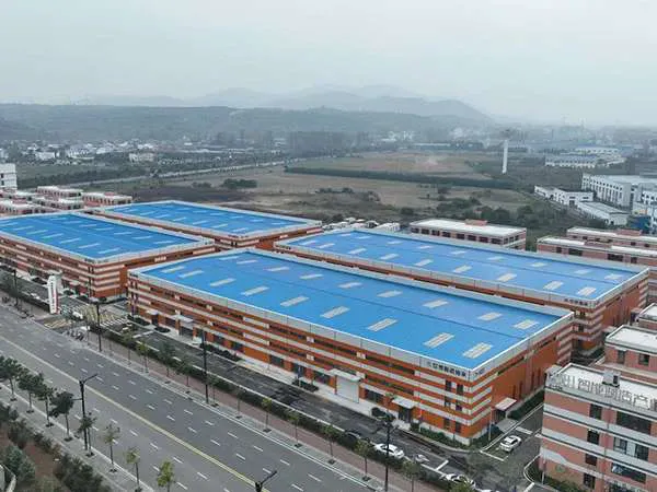
This makes PPAL an ideal choice for applications ranging from building facades and roofing to automotive panels and industrial machinery.
Step-by-Step Manufacturing Process of PPAL
Producing high-quality pre-painted coated aluminum sheets involves precision engineering and strict quality control. Here’s an in-depth look at the key stages:
1. Aluminum Substrate Preparation
High-grade aluminum coils are cleaned and degreased to remove oil, dust, and impurities. This ensures the paint layers adhere perfectly and provides a smooth, defect-free surface.
2. Chemical Treatment & Surface Conditioning
The aluminum surface undergoes anodizing or conversion coating, improving corrosion resistance and creating a slightly rough texture that enhances paint adhesion.
…
For more detailed information on the manufacturing process of pre-coated aluminum sheets, please click to visit: https://www.dw-al.com/a/news/manufacturing-process-of-pre-coated-aluminum-sheet.html