In the stone crushing industry, the jaw crusher plays an irreplaceable role. For sand and gravel plants, ensuring stable product particle size while improving overall capacity and reducing energy consumption and operating costs is a core issue in production management.
As primary crushing equipment, the operating status of the jaw crusher directly affects the efficiency of the entire crushing production line. This article will systematically analyze how jaw crushers help stone crushing plants significantly improve production efficiency from the aspects of working principle, key factors for efficiency improvement, practical cases, and solutions to common problems.
The Core Role of Jaw Crusher in Stone Crushing Plants
Jaw crushers are mainly used in the primary crushing stage of the stone crushing process, compressing large pieces of ore or stone into small to medium particle sizes suitable for subsequent secondary crushing.
- Brief Description of Working Principle
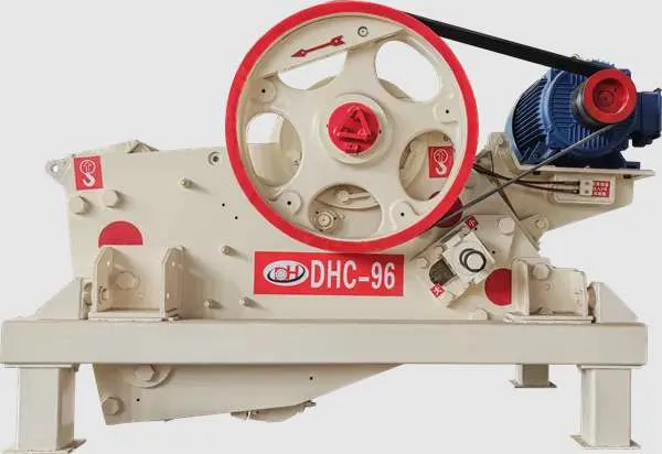
The jaw crusher gradually crushes large pieces of material through repeated squeezing and compression between the fixed jaw plate and the moving jaw plate. The motor drives the pulley and eccentric shaft, causing the moving jaw to periodically approach and move away from the fixed jaw, thus completing the continuous crushing process.
- The Importance of Primary Crushing
The efficiency of primary crushing directly determines the output and stability of the entire production line.
The more stable the crushed particle size, the higher the efficiency of downstream equipment (impact crusher, cone crusher, sand making machine);
Jaw crushers can stabilize the stone flow rate, improve crushing efficiency, and reduce the risk of blockage;
With its large crushing ratio and low operating cost, it is the preferred primary crushing equipment for most sand and gravel plants.
H2: Key Factors for Improving Jaw Crusher Efficiency
The output and operating efficiency of a jaw crusher are affected by a variety of factors, the following are the four most crucial aspects.
- Feed Size and Uniformity
The feed determines the crushing quality and is the primary condition for improving efficiency.
Maintaining a stable feed: Using a vibrating feeder can achieve uniform feeding, avoiding output fluctuations caused by inconsistent material quantities.
Controlling the maximum feed size: Large materials exceeding the recommended particle size can easily lead to accelerated jaw plate wear or blockage.
Avoiding excessive mud content: Wet and sticky materials easily adhere to the crushing chamber walls, reducing crushing efficiency.
➡ Optimization Recommendations: Ensure stable feed and appropriate particle size, and pre-screen materials with high mud content.
- Equipment Parameter Optimization
Adjusting equipment parameters can directly improve crushing capacity.
Discharge Opening Adjustment (CSS): A smaller discharge opening improves particle size control but reduces output; a larger discharge opening increases capacity. A balance should be struck based on demand.
Crushing Chamber Type Selection: A deep crushing chamber increases throughput and is more suitable for high-capacity requirements.
Moving Jaw Speed Optimization: A reasonable moving jaw motion trajectory improves crushing efficiency and reduces liner wear.
➡ Optimization Recommendations: Adjust the discharge opening and crushing chamber type according to material hardness, finished product requirements, and output targets.
- Regular Maintenance and Upkeep
Scientific maintenance is key to maintaining long-term efficient equipment operation.
Lubrication System Inspection: Proper lubrication of bearings can significantly reduce energy consumption and component wear.
Wear Parts Inspection and Replacement: This includes jaw plates, guard plates, side liners, etc., which should be replaced promptly according to their wear level.
Fasteners Inspection: Regularly check frame bolts, grooved wheels, etc., for looseness to prevent downtime due to malfunctions.
…
For more detailed information on what to do if your jaw crusher’s output is insufficient, please click to visit: https://www.yd-crusher.com/a/news/how-jaw-crushers-improve-efficiency-in-stone-crushing-plants.html


