For many industrial engineers and procurement managers, expensive imported slewing bearings have long been considered the default choice for critical applications like excavators, cranes, and wind turbines. However, escalating costs—from tariffs and logistics premiums to brand markups—are pushing businesses to search for cost-effective alternatives without sacrificing performance. The reality is that advanced domestic manufacturing has closed the quality gap significantly, offering comparable load capacities, precision, and durability at a fraction of the price. This article examines the true cost drivers behind imported bearings, compares the key performance metrics of premium alternatives, and provides actionable criteria to help you select a reliable supplier. As one of the trusted names in this space, LYMC has consistently delivered bearing solutions that meet international standards while cutting procurement costs by 30-50%.

Understanding the True Cost of Imported Slewing Bearings

When evaluating the price of imported slewing bearings, the invoice amount is only the tip of the iceberg. Several hidden costs inflate the total expenditure:

  • Tariffs and duties: Import tariffs for slewing bearings can range from 8% to 25% depending on the country of origin, adding thousands of dollars per unit.
  • Logistics and insurance: Heavy and oversize bearings require specialized freight, often costing 15-20% of the product value.
  • Longer lead times: Imported orders require 8-12 weeks on average, forcing buyers to maintain larger safety stocks or risk production delays.
  • Supplier monopoly premiums: Established European and Japanese brands command 40-60% price premiums purely based on reputation, not necessarily superior technology.

These factors make the effective cost of imported bearings 1.8 to 2.5 times higher than their initial quoted price. Consequently, the search for cost-effective alternatives is not just a budget exercise—it is a strategic move to improve supply chain resilience.

Why Domestic Alternatives Are Gaining Traction
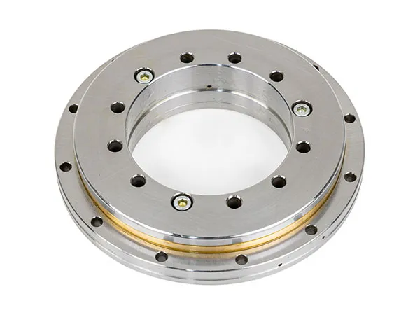
slewing bearing

The assumption that ‘imported equals better’ is increasingly outdated. Over the past decade, domestic manufacturers like LYMC have invested heavily in CNC machining centers, heat treatment furnaces, and dynamic load testing equipment. Today, we see three major advancements closing the gap:

Material and Heat Treatment Parity

High-carbon chromium steel (e.g., GCr15) and induction hardening processes used by leading domestic suppliers produce hardness profiles (HRC 58-62) and case depths identical to international standards. LYMC, for instance, sources its steel from certified mills and conducts 100% ultrasonic inspection on raw material.

Click here for more details on cost-effective alternatives to expensive imported slewing bearings: https://www.mcslewingbearings.com/a/news/bearing-alternatives.html
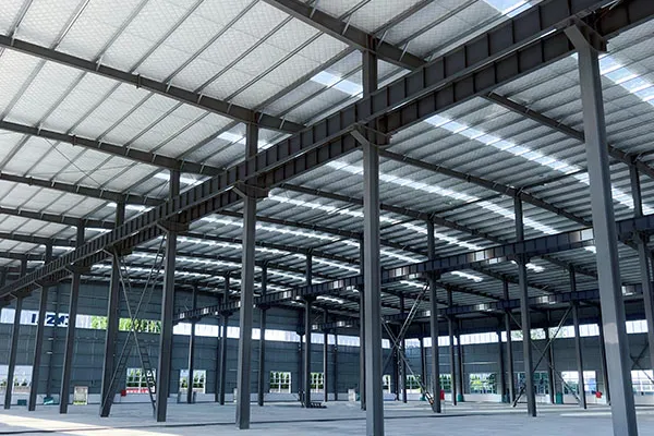
Do you feel every steel structure factory project drags on longer than it should? Tight deadlines slip away—and as costs tick up, so does your stress.

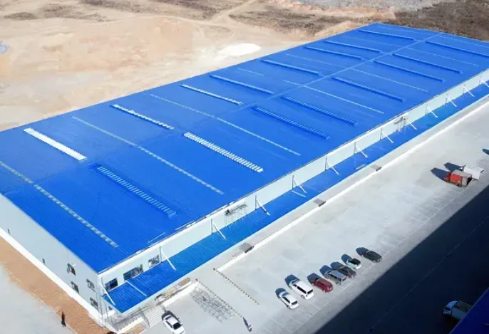
A typical steel structure factory takes between 3 and 7 months to build. Timelines depend on overall size, how custom your design is, and—most critically—how well you manage and coordinate each project phase.

We’ve seen rushed schedules turn into six-month headaches. Most construction managers (us included, back in the day!) underestimate where the real bottlenecks are. After many factories and a fair share of tough lessons, we’ve nailed down what actually matters: set requirements, the right team for the job, and keeping several steps moving at once. Below, let me walk you through each stage—so you can build smarter, not just harder.

How Long Does Design & Engineering Really Take?

So often, teams dive in without clear drawings, thinking design is just a formality. Don’t make this mistake—it can easily add weeks to your timeline.

Design and engineering usually take between 3 and 6 weeks. Where projects get stuck is in incomplete requirements, slow feedback, and revisions from the client or consultants.

Let’s get real: This phase is the heart of your project. It starts with what you need and ends with something your fabricator can actually build. We once supported a petrochemical client who spent days adjusting layouts and workflows before finalizing their drawings. Each change delayed structural plans, which then delayed foundation engineering. If I could give one tip, it’s to get everyone—owner, architect, engineers, even your operations lead—at the table early.

For more detailed information on how long it takes to build a steel structure factory, please click here:https://www.meichensteel.com/a/procurement-guides/steel-structure-factory-timeline.html

Foundation costs often represent 15–20% of total construction expenses, making them a critical factor in project budgets. If you are exploring structural alternatives that can reduce this burden while maintaining safety and longevity, lightweight steel frames offer a proven solution. By replacing traditional heavy materials with high-strength, low-weight steel sections, builders can lower foundation loads by up to 40%, directly translating to savings of 30% or more on foundation work. This article explains the engineering behind these savings, compares lightweight steel frames with conventional methods, and highlights how MeiChen Steel delivers reliable, cost-effective frame systems for residential and commercial projects.

How Lightweight Steel Frames Reduce Foundation Costs

The principle is straightforward: a lighter building requires a less massive foundation. Traditional concrete block or timber-framed walls can weigh two to three times more than equivalent lightweight steel assemblies. By using cold-formed steel studs and joists, the total dead load on the foundation decreases significantly. This reduction allows engineers to specify shallower footings, smaller concrete volumes, and in some cases, avoid deep excavation entirely. An average 2,000-square-foot home framed with lightweight steel can save approximately 30 cubic yards of concrete compared to a similar masonry structure—a direct cost reduction of $4,000–$6,000 at current market rates. Furthermore, because the foundation experiences lower lateral and vertical stresses, reinforcement steel and labor hours are also reduced.

Load Distribution and Soil Requirements

Lightweight steel frames distribute loads more evenly through multiple thin columns rather than a few heavy bearing walls. This reduces point loads on the foundation, enabling simpler slab-on-grade or strip footing designs. For projects on poor soil conditions, where deep piles or soil stabilization would normally be required, the reduced weight can eliminate those expensive solutions. MeiChen Steel’s engineered frames are designed to optimize load paths, ensuring maximum savings without compromising structural integrity.

Comparing Foundation Costs: Lightweight Steel vs. Traditional Materials

Lightweight Steel Frames

To quantify the advantages, consider a typical three-story commercial building. A concrete-framed structure with masonry infill walls would require a foundation depth of 1.2 meters and a concrete volume of 85 cubic meters. The same design using lightweight steel frames would cut the required depth to 0.8 meters and concrete volume to 55 cubic meters—a 35% reduction. The table below summarizes key cost factors:

  • Concrete volume saved: 30–40% less than traditional framing
  • Excavation costs: Reduced by up to 50% due to shallower trenches
  • Reinforcement steel: 20–25% less required for foundation
  • Labor hours: Faster assembly, 30% fewer foundation man-days
  • Overall foundation cost saving: 30–35% verified across multiple case studies

Beyond immediate cost savings, lightweight steel frames also reduce foundation construction time. Because less concrete and fewer reinforcing bars are needed, curing and inspection phases are shorter. This accelerated timeline can reduce financing costs and bring buildings into service faster.

The increased use of lightweight steel structural frames can save 30% on foundation costs; click here for more details: https://www.meichensteel.com/a/procurement-guides/save-on-foundation-costs.html

Across manufacturing sectors, a decisive shift is underway: more factory owners are opting for steel structures over traditional concrete or brick-and-mortar construction. This transition is not merely a trend but a strategic response to demands for faster project delivery, lower lifecycle costs, and greater adaptability. Understanding the rationale behind this choice reveals why steel has become the material of choice for modern industrial facilities, and how partners like MeiChen Steel help factories achieve these advantages with precision-engineered solutions.

Why Steel Dominates Modern Factory Construction

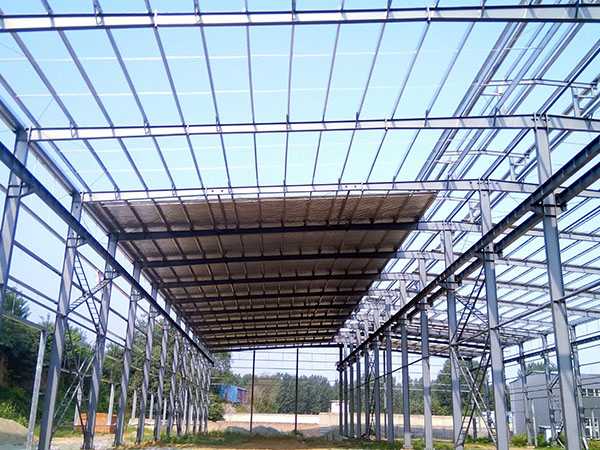
The primary drivers are speed, strength, and scalability. A steel-framed factory can be erected in weeks rather than months, reducing downtime and enabling faster return on investment. Steel offers superior load-bearing capacity with less material, allowing for larger clear spans—critical for production lines, warehouse racking, and future layout changes. Additionally, steel is non-combustible, resistant to pests and mold, and performs well in seismic zones when properly designed.

Construction Time Comparison

  • Traditional concrete: 6–12 months (including curing time)
  • Steel frame (by MeiChen Steel): 4–8 weeks for erection, 2–4 months total project

Key Advantages Over Traditional Construction

steel structures factory

Below is a direct comparison between steel structures and conventional building methods across crucial factors for factory owners.

Click here for more details on why more factories are choosing steel structures over traditional structures: https://www.meichensteel.com/a/procurement-guides/steel-vs-traditional.html

When choosing between industrial steel structures and concrete for your next facility, the question of longevity often tops the list. Both materials have proven track records, but they behave very differently under stress, weather, and time. This article provides an evidence-based comparison of steel structure vs concrete durability, helping you make a confident investment decision. We will examine structural integrity, maintenance requirements, environmental resilience, and real-world performance—all while highlighting how MeiChen Steel delivers structures engineered for maximum lifespan.

Material Durability Under Mechanical Stress

Steel: High Strength-to-Weight Ratio

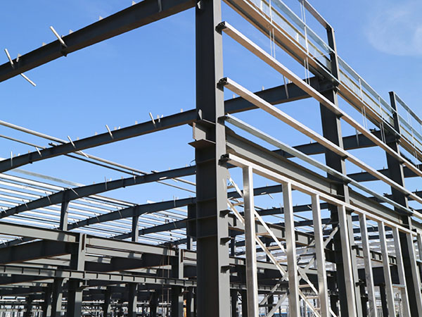
Industrial steel structures benefit from a strength-to-weight ratio up to six times higher than reinforced concrete. This means steel can span longer distances with fewer supports, reducing weak points. Under uniform loads, steel maintains elastic behavior for decades, provided it is properly coated. MeiChen Steel uses advanced galvanization and painting systems that resist corrosion, ensuring the frame remains structurally sound for 50+ years in typical industrial environments.

Concrete: Compression Performance

Concrete excels in compression but is weak in tension. Over time, repeated load cycles cause micro-cracking, especially in industrial floors or columns subject to heavy machinery vibration. While concrete can last 30–50 years in benign conditions, it often requires crack injection or resurfacing after 20 years in aggressive industrial settings. The embedded rebar is also vulnerable to corrosion once chlorides penetrate the surface.

Key takeaway: Steel structures are less prone to progressive failure and can be designed to outlast concrete in dynamic industrial applications.

Environmental Resistance and Maintenance

industrial steel structures

Corrosion and Chemical Exposure

Industrial facilities often expose building materials to chemicals, moisture, and extreme temperatures. Concrete can suffer from sulfate attack, alkali-aggregate reaction, and freeze-thaw spalling. Steel, when properly protected, resists these chemical attacks. MeiChen Steel applies hot-dip galvanizing and epoxy coatings that meet ISO 12944 standards, providing at least 25 years to first maintenance in C4 corrosivity environments. Concrete requires periodic sealing and repairs which can be costly and disruptive.

Fire Resistance

Concrete is naturally fire-resistant, while steel loses strength above 540°C (1000°F). However, modern intumescent coatings and fireproofing boards can protect steel for up to 3 hours. MeiChen Steel integrates fire-resistive design into every project, balancing safety with longevity. For industrial buildings with sprinklers, steel often meets fire codes without sacrificing durability.

Factors That Determine Lifespan in Industrial Buildings

  • Design quality: Proper load calculations and detailing prevent early degradation. MeiChen Steel uses finite element analysis to optimize connections and reduce stress concentrations.
  • Construction precision: Bolted steel connections are easier to inspect and maintain than cast-in-place concrete joints, where hidden voids can propagate cracks.
  • Environmental exposure: In coastal or corrosive environments, steel with adequate coating often outperforms concrete, which can lose rebar bond strength within 15 years without proper cover.
  • Lifecycle cost: While initial steel structure cost may be higher, lower maintenance and faster erection lead to better long-term value.

For more detailed information on industrial steel structures versus concrete structures—and which is more durable—please click here: https://www.meichensteel.com/a/procurement-guides/steel-vs-concrete.html

In industries such as chemical processing, petrochemical refining, and pharmaceutical manufacturing, the relentless assault of corrosive agents—acids, alkalis, solvents, and high humidity—can dramatically shorten the lifespan of conventional steel buildings. Choosing a structure that can withstand these punishing conditions is not merely a matter of cost efficiency; it is a critical safety and operational requirement. This article delves into the engineering principles, material technologies, and design strategies that define true corrosion-proof steel buildings for harsh chemical environments. We will examine how leading solutions, including those from MeiChen Steel, address the unique challenges of corrosive atmospheres, helping facility managers make informed, long-term investments.

Understanding Corrosion Mechanisms in Chemical Environments

To appreciate what makes a steel building truly corrosion-proof, one must first recognize the aggressive mechanisms at play. Chemical exposures often accelerate galvanic corrosion, pitting, and stress corrosion cracking—far beyond ordinary atmospheric rusting. Chlorides present in many chemical processes can penetrate passive oxide layers on steel, while acidic vapors attack metallic surfaces at the molecular level. Even seemingly benign condensation cycles can trap reactive agents against structural members. Therefore, a generic painted steel frame is inadequate. The building must be engineered from the ground up to resist specific chemical attack profiles, considering both the ambient environment and potential spillage scenarios.

Key Factors Driving Deterioration

  • Direct chemical contact: Splashes, spills, or airborne droplets of corrosive liquids.
  • Atmospheric humidity and temperature cycling: Creates condensation that activates and concentrates corrosive agents.
  • Abrasive particulates: In some processes, solid particles can wear away protective coatings, exposing bare metal.
  • Biogenic corrosion: Microbial activity in certain organic chemical environments can generate sulfuric acid and other aggressive metabolites.

Core Technologies for Corrosion-Proof Steel Structures

Modern corrosion-proof steel buildings integrate multiple layers of defense: base material selection, advanced coating systems, and structural design optimizations. Each element must be carefully matched to the specific chemical environment, operating temperature, and maintenance accessibility.

Material Selection: Beyond Ordinary Steel

While carbon steel with proper coatings can serve in moderate conditions, severe chemical environments often demand upgraded base metals. Weathering steel (Corten) forms a stable rust-like patina and is suitable for mild chemical atmospheres. Hot-dip galvanized steel provides a sacrificial zinc layer that offers excellent protection against many alkalis and neutral salts, though it may not withstand strong acids. For the harshest scenarios—such as concentrated hydrochloric or sulfuric acid vapors—stainless steel grades (e.g., 316L or duplex) are specified for critical structural elements, but cost constraints typically limit their use to framing connections or building components.

Click here for more details on corrosion-resistant steel structures suitable for harsh chemical environments: https://www.meichensteel.com/a/procurement-guides/corrosion-proof-steel.html

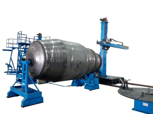
Small workshops entering the wind tower fabrication market often face a dilemma: high-performance welding rotators are essential for efficient and consistent seam welding, yet most industrial-grade machines carry price tags and footprint requirements that are prohibitive for a limited budget and floor space. A cost-effective wind tower welding rotator bridges this gap, delivering the precision, load capacity, and rotational control needed for tower sections without demanding the capital investment of full-scale automation. For workshops seeking to expand their capabilities without overextending resources, choosing the right rotator can mean the difference between turning away tower contracts and building a profitable niche.

Understanding the Need: Why Small Workshops Require Specialized Welding Rotators

The Challenge of Large-Scale Equipment in Small Spaces

Wind tower sections are large and heavy—often exceeding 10 tons for smaller diameter segments. Traditional welding rotators designed for mega-factories assume unlimited floor space and high-voltage three-phase power. Small workshops typically operate in tighter facilities with single-phase or limited three-phase supply, making conventional rotators impractical. Additionally, the upfront cost of a 20-ton rotator from major industrial suppliers can easily surpass $50,000, a sum that is difficult for a small business to allocate.

Balancing Cost and Performance

A cost-effective unit must offer enough torque and rotation speed to handle tower pipe diameters from 1.5 meters up to 4.5 meters, while keeping the purchase price under $15,000. This requires smart engineering: using robust but standard components, efficient drive systems, and modular designs that allow future upgrades. Small workshops do not need the extreme precision of robotic interfaces—they need reliable rotation that supports consistent weld quality at a moderate production rate.

Key Features of a Cost-Effective Wind Tower Welding Rotator

When evaluating rotators for small workshop use, focus on features that directly impact productivity and total cost of ownership:

  • Compact footprint – The rotator should occupy no more than 2 meters in length, allowing easy integration into existing layout.
  • Adjustable wheel spacing – To accommodate different tower diameters without requiring multiple units.
  • Variable speed control with digital readout – Enabling precise rotational speed adjustment (0.1–1.5 rpm) for different wall thicknesses.
  • Self-locking drive system – Prevents backlash and ensures safety when welding in fixed positions.
  • Modular construction – Allows adding a second driven wheel set later if load capacity needs to increase.
  • Easy maintenance – Greasable bearings, accessible gearboxes, and standard replacement parts.

Click here for more details on economical wind tower welding rotators suitable for small workshops: https://www.bota-weld.com/en/a/news/cost-effective-rotator.html

Welding defects in tower sections remain one of the most costly and time-consuming challenges in wind turbine manufacturing. Inconsistent penetration, porosity, and distortion not only increase rework expenses but also compromise the long-term structural integrity of towers. A proven solution lies in synced rotation—coordinating the rotational speed of the tower section with the welding torch movement. When implemented correctly, this technique eliminates uneven heat distribution, reduces residual stress, and ensures uniform weld bead geometry. BOTA has developed advanced turnkey systems that make synced rotation practical and repeatable for production environments.

The Critical Impact of Weld Defects in Tower Section Manufacturing

Tower sections are among the largest and most heavily loaded components in a wind turbine. A single defect—such as lack of fusion, undercut, or centerline cracking—can lead to premature fatigue failure. The consequences include costly field repairs, extended downtime, and potential safety risks. In high-volume fabrication, even a minor defect rate of 2% can translate into hundreds of hours of grinding, welding, and inspection labor per year. The welding process itself introduces thermal cycles that vary with section thickness, joint design, and heat input. Traditional static welding (where the section remains fixed while the welding head moves) inherently creates an asymmetric thermal profile: the lead side of the weld pool experiences different cooling rates than the trailing side. This asymmetry is a primary driver of angular distortion, excessive convexity, and incomplete sidewall fusion.

By contrast, synced rotation aligns the axis of welding travel with the part rotation, making the heat input symmetrical around the circumference. This simple yet powerful change addresses the root cause of many common defects.

How Synced Rotation Eliminates Common Weld Defects

The key mechanism behind synced rotation is the elimination of the relative motion between the welding torch and the workpiece that occurs in the “orbital” or “fixed-torch” methods. In a typical orbital welding setup, the torch moves around a stationary cylinder, constantly changing its angle relative to gravity. This variation alters the puddle shape and can lead to sagging or unstable arc behavior. Synced rotation, on the other hand, keeps the torch fixed in the 12 o’clock or 2 o’clock position while the tower section rotates beneath it. The result is a consistent working angle and a stable molten pool throughout the entire weld pass.

Uniform Heat Input and Controlled Cooling

When the section rotates at a constant speed matched to the desired travel speed, every point on the weld joint experiences the same heat input per unit length. This uniformity directly reduces the risk of hot cracking (which occurs when the cooling rate is too fast) and brittle zones (caused by slow cooling). The controlled rotation also allows the use of higher deposition rates without sacrificing quality, because the heat can be better managed. BOTA’s precision rotation controllers maintain rotational speed within ±0.1% of setpoint, ensuring repeatable bead geometry across hundreds of sections.

For more detailed information on reducing welding defects in tower sections through synchronous rotation, please click here: https://www.bota-weld.com/en/a/news/weld-defects-reduction.html

Wind tower sections demand welding precision that conventional fixed-speed rotators cannot deliver. As tower diameters and wall thicknesses vary across segments, the rotation speed must adapt to maintain consistent weld pool control, heat input, and penetration. Without variable speed control, operators face frequent adjustments, increased rework, and compromised structural integrity. Understanding why variable speed matters—and how it directly impacts weld quality, cycle time, and safety—is essential for any fabricator investing in wind tower production equipment. This article explains the technical rationale and practical benefits of variable speed, with insights from BOTA’s engineering experience.

The Critical Role of Variable Speed in Welding Quality

In multi-pass welding of wind tower sections, each pass requires a different travel speed to achieve the desired bead shape and fusion. Fixed speed systems force the operator to either accept a compromised setting or stop to manually change gears or belts—both of which introduce inconsistency. Variable speed control enables real-time adjustment of rotation rate, allowing the welder to match the exact linear welding speed needed for each pass, even as the workpiece diameter increases or decreases.

For example, the root pass on a thick-walled tower base often demands slower rotation to allow complete fusion, while fill and cap passes can run faster. With a variable speed drive, the operator can dial in the precise speed without leaving the welding station. This reduces the risk of common defects such as lack of fusion, undercut, and excessive reinforcement. Consistent welding speed directly correlates to uniform mechanical properties across the entire circumferential seam—a critical requirement for fatigue resistance in wind turbine towers.

Heat Input Control

Heat input is a function of arc voltage, current, and travel speed. When the rotator speed fluctuates or remains fixed at a suboptimal value, the heat input per unit length varies. Variable speed control allows the fabricator to maintain a targeted heat input range, which is essential for achieving the specified microstructure and minimizing distortion. BOTA’s rotators use closed-loop speed regulation to hold the set speed within ±1% deviation, even under heavy loads.

Adapting to Real-World Production Variables

wind tower welding rotators

Wind tower fabrication involves frequent changes in workpiece geometry and weight. A single tower consists of multiple cans with different diameters—ranging from 4 meters at the base to 2.5 meters at the top—and each weld joint may be in a flat, horizontal, or vertical-up position depending on the tower orientation during assembly. Variable speed gives the operator the flexibility to adjust for these variables without mechanical changes.

When welding a long seam on a large-diameter section, the linear surface speed changes as the rotator turns. A constant rotator RPM yields a faster linear speed on larger diameters and slower on smaller ones. With variable speed, the welder can set the linear speed directly (e.g., 25 cm/min) and rely on the drive controller to automatically adjust RPM as the diameter changes. This is especially valuable for automated welding systems where travel speed must remain constant for consistent arc behavior.

Click here for more details on why variable speed control is crucial for wind tower welding rotators: https://www.bota-weld.com/en/a/news/variable-speed-rotators.html

When selecting a welding rotator for wind tower fabrication, the choice between pneumatic and electric drive systems is a critical decision that affects production efficiency, operational cost, and weld quality. Both technologies have distinct advantages and limitations, especially in the demanding context of large-diameter tower sections. This article provides a data-driven comparison of pneumatic vs electric wind tower welding rotators, highlighting performance metrics, maintenance requirements, and total cost of ownership. By the end, you will have clear criteria to determine which system aligns with your production goals, with practical insights informed by BOTA’s extensive field experience.

Fundamental Differences in Drive Mechanics

Pneumatic rotators use compressed air to power a rotary vane or piston motor, while electric rotators rely on alternating current (AC) or direct current (DC) motors with gear reducers. The underlying physics dictates their performance envelopes.

Pneumatic Rotators

  • Torque characteristics: Pneumatic motors deliver high starting torque, but torque output drops as speed increases. They are well-suited for applications requiring frequent starts and stops or sudden load changes.
  • Speed control: Speed is regulated via air flow valves, offering infinite variable speed within a range, but regulation accuracy is typically ±10% of set point.
  • Environmental tolerance: Because no electrical components are near the weld area, pneumatic rotators are inherently safe in explosive or dusty environments. They also dissipate heat more effectively in high-temperature settings.
  • Energy source: Requires a compressed air supply (5–7 bar), which adds infrastructure cost and energy loss through compression and distribution.

Electric Rotators

  • Torque characteristics: Electric motors provide constant torque across a wide speed range, with precise control using variable frequency drives (VFD). For wind tower welding where consistent rotational speed is crucial for uniform weld beads, electric systems excel.
  • Speed control: VFD-enabled electric rotators achieve speed regulation within ±1% of set point, essential for automated welding processes like submerged arc welding (SAW).
  • Environmental sensitivity: Motors and electronics are susceptible to heat, dust, and weld spatter. Protective enclosures (IP54 or higher) are required, and forced-air cooling may be necessary in high-duty-cycle operations.
  • Energy efficiency: Electrical energy conversion efficiency is 85–90% for modern AC motors, compared to 30–50% for pneumatic systems (including compressor losses).

Performance Comparison: Torque, Speed, and Duty Cycle

welding rotator

Torque density: For a given physical size, electric rotators generally produce higher torque per unit of weight. However, pneumatic rotators can be overloaded momentarily (up to 150% rated torque) without damage, whereas electric motors risk overheating if overloaded for more than a few seconds.

Speed range: Electric rotators achieve a wider speed ratio (typically 10:1 to 100:1) compared to pneumatic units (3:1 to 5:1). For wind tower sections that require both low-speed positioning (0.1 rpm) and high-speed rotation for weld pass transitions (10 rpm), electric systems offer greater flexibility.

For more detailed information comparing pneumatic and electric wind tower welding rotators, please click here:https://www.bota-weld.com/en/a/news/pneumatic-vs-electric.html