When laboratory research demands precision, consistency, and reliability at elevated temperatures, the choice of crucible material becomes a critical factor that can significantly affect experimental outcomes. High-purity graphite crucibles have emerged as the preferred containment vessel for a wide range of high-temperature applications, from metal melting and alloy synthesis to thermal analysis and sample preparation. Unlike standard-grade graphite, high-purity variants (typically with carbon content exceeding 99.99%) eliminate the risk of contamination and ensure reproducible results. In this article, we explore why high-purity graphite crucibles are indispensable for modern lab research, highlight the key advantages offered by Cangzhou Carbon, and provide a practical guide to selecting the right crucible for your specific needs.

Why High-Purity Graphite Crucibles Are Critical for Lab Research

The integrity of any high-temperature experiment hinges on the purity of the containment vessel. Even trace amounts of metallic or inorganic impurities can leach into the sample, skewing analytical data or catalyzing unintended reactions. High-purity graphite crucibles—typically manufactured from synthetic graphite with total ash content below 50 ppm—provide an inert, non-contaminating environment that preserves the chemical composition of the sample.

Impact of Purity on Experimental Accuracy

For techniques such as inductively coupled plasma mass spectrometry (ICP-MS) or atomic absorption spectroscopy (AAS), crucible blanks must introduce no detectable interference. Standard graphite crucibles often contain residual metals like iron, silicon, or aluminum, which can generate background signals. High-purity crucibles, such as those produced by Cangzhou Carbon under strict quality control, undergo a purification process (often via high-temperature halogenation) to reduce impurity levels to parts-per-million or even parts-per-billion ranges. This ensures that the crucible itself does not become a variable in your results.

Thermal Stability and Oxidation Resistance

Laboratory processes frequently involve rapid heating and cooling cycles, extreme temperatures (up to 3000°C in inert atmospheres), and aggressive chemical environments. High-purity graphite exhibits superior thermal shock resistance due to its low coefficient of thermal expansion and high thermal conductivity. Additionally, when used in vacuum or protective atmosphere, high-purity graphite crucibles maintain structural integrity without cracking or spalling, which is essential for reproducible melt preparation and solid-state reactions.

Key Features of Cangzhou Carbon High-Purity Graphite Crucibles

Graphite

Cangzhou Carbon has established itself as a reliable supplier for laboratory-grade graphite crucibles through decades of manufacturing expertise. Their products are engineered to meet the rigorous demands of scientific research. Below are the standout features that differentiate Cangzhou Carbon crucibles from commodity alternatives:

  • Ultra-high purity (>99.99% carbon): Each batch is tested for trace element content, ensuring minimal contamination for sensitive applications such as precious metal analysis and semiconductor research.

For more detailed information on high-purity graphite crucibles for laboratory research applications, please click here:https://www.czgraphite.com/a/news/high-purity-crucibles.html

Every foundry or metalcasting facility knows the frustration of a cracked crucible: production stops, a pricey replacement is needed, and the risk of contamination rises. The root cause is often thermal shock — the rapid temperature changes that typical crucibles cannot withstand. This article explains how thermal shock resistant crucibles, particularly those manufactured by Cangzhou Carbon, address this failure point and deliver measurable cost savings. By understanding the mechanism and long-term value, you can make an informed procurement decision that protects your bottom line.

What Makes a Crucible Thermal Shock Resistant?

Thermal shock resistance is the ability of a material to resist cracking under sudden temperature gradients. In crucibles, this property is critical when they are repeatedly heated and cooled during melting, holding, or pouring cycles. Standard clay-graphite or silicon carbide crucibles may develop micro-cracks after only a few cycles, especially if they are preheated unevenly. In contrast, thermal shock resistant grades incorporate optimized grain size distribution, higher carbon content, and advanced bonding systems that allow the material to absorb thermal stresses without failure. Cangzhou Carbon’s crucibles use a proprietary formula that maintains structural integrity even when exposed to direct flame on one side and cold metal on the other.

The Hidden Costs of Crucible Cracking

Graphite

Many operators underestimate the true financial impact of a cracked crucible. Beyond the immediate replacement cost, several indirect expenses accumulate:

  • Unplanned downtime: A crack forces an immediate halt to production while the crucible is swapped out. Depending on the size, this can cost hundreds or thousands of dollars per hour in lost output.
  • Metal contamination: Cracks allow slag and gases to penetrate the crucible wall, contaminating the melt. Scrapped batches add material waste and reprocessing costs.
  • Accelerated furnace wear: Leaking molten metal can damage the furnace lining, leading to expensive refractory repairs.
  • Safety risks: A catastrophic crucible failure may cause hot metal spills, endangering personnel and requiring costly cleanup.

These factors often make the total cost of a standard crucible 2–3 times higher than its purchase price over a year of operation.

How Thermal Shock Resistant Crucibles Deliver Net Savings

Choosing a thermal shock resistant crucible from Cangzhou Carbon directly addresses each cost driver. Here is a breakdown of the comparative advantages:

Extended Service Life

While a conventional crucible may last 30–60 heats before cracking, a properly selected thermal shock resistant grade can easily exceed 120 heats in the same application. Fewer replacements mean lower consumables costs and reduced labor for crucible changeouts.

Click here for more details on how thermal shock-resistant crucibles save costs by preventing cracking:https://www.czgraphite.com/a/news/thermal-crucible-cost.html

Selecting the optimal graphite crucible for induction furnace melting directly impacts melt quality, energy efficiency, and operational cost. With numerous options on the market, engineers and procurement specialists need a reliable benchmark to evaluate thermal conductivity, oxidation resistance, and mechanical strength. This guide provides a technical comparison of high-performance crucibles, highlighting the critical parameters that define true durability. Whether you are scaling up production or replacing consumables, understanding these factors ensures you invest in a crucible that withstands extreme thermal cycling and aggressive slag conditions. As an industry leader, Cangzhou Carbon has engineered crucibles specifically for induction furnaces, combining advanced isostatic pressing with high-purity raw materials.

Why Graphite Crucibles Dominate Induction Melting

Induction furnaces generate intense heat through eddy currents, requiring a crucible material that offers both excellent electrical conductivity and thermal shock resistance. Graphite meets these demands due to its unique crystalline structure, which provides high thermal conductivity (typically 120-180 W/mK) and low thermal expansion. Unlike metal crucibles, graphite does not contaminate molten alloys and can withstand temperatures exceeding 1600°C. However, not all graphite crucibles perform equally under cyclic heating and cooling. The best crucibles exhibit minimal porosity, consistent density, and a protective oxidation layer that extends service life.

Key Performance Indicators for Induction Furnace Crucibles

  • Thermal Conductivity: Higher values reduce heating time and energy consumption. Premium crucibles from Cangzhou Carbon maintain thermal efficiency above 150 W/mK.
  • Oxidation Resistance: A dense surface and antioxidant coating prevent weight loss during high-temperature exposure. This directly correlates with crucible lifespan.
  • Mechanical Strength: Compressive and flexural strength determine resistance to cracking during rapid temperature changes. Minimum 40 MPa flexural strength is recommended for induction use.
  • Ash Content: For critical alloys (e.g., precious metals, superalloys), ash content must be below 0.1% to avoid contamination. Cangzhou Carbon offers ultra-low ash grades.
  • Dimensional Stability: Minimal shrinkage after repeated use ensures consistent melt capacity and prevents furnace damage.

Selecting the Best Crucible: Comparative Analysis

Graphite

When evaluating suppliers, compare not only price but also material grade and manufacturing process. Isostatically pressed graphite crucibles deliver superior homogeneity compared to die-molded or extruded alternatives.

Click here for more detailed information on the best graphite crucibles for induction furnace melting: https://www.czgraphite.com/a/news/best-graphite-crucibles.html

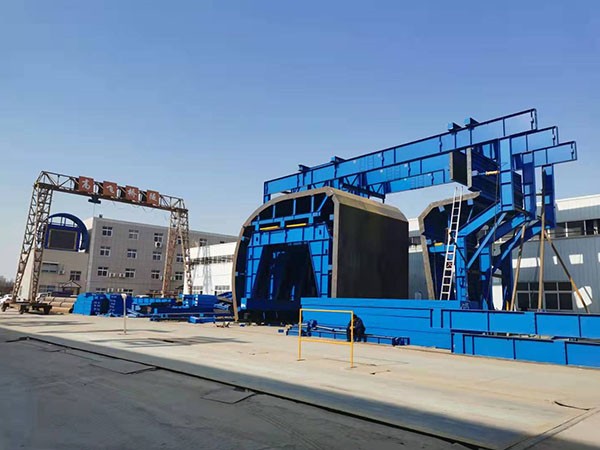
Selecting the appropriate tunnel formwork system is a critical decision that directly impacts construction efficiency, safety, and overall project costs. For contractors and project managers evaluating formwork solutions, the choice between lightweight and heavy-duty tunnel formwork often determines the success of large-scale infrastructure or building projects. This article provides a professional, data-driven comparison to help you make an informed decision, drawing on industry best practices and the expertise of formwork manufacturers like Gaofei.

Understanding the Fundamental Differences

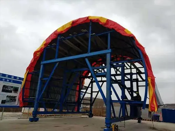
Lightweight tunnel formwork typically uses aluminum alloy or high-strength steel with thinner profiles, designed for manual handling and fast assembly. Heavy-duty tunnel formwork, by contrast, features thicker steel sections, reinforced frames, and often integrates hydraulic systems for movement and stripping. The core distinction lies in load-bearing capacity, weight, and the intended application scale.

Material and Construction

Lightweight systems usually incorporate aluminum beams and plywood panels, making them easy to transport and assemble without heavy machinery. Heavy-duty systems use steel sections (often S355 grade), welded joints, and full-height steel panels, capable of supporting wet concrete pressures exceeding 80 kN/m². Gaofei’s heavy-duty line, for example, utilizes hot-rolled steel with anti-corrosion coating for longevity in harsh tunnel environments.

Weight and Logistics

A standard lightweight tunnel formwork panel (2.5m x 3m) weighs around 250-350 kg, allowing crane-free repositioning using dollies or simple lifting equipment. Heavy-duty panels of similar dimensions can weigh 800-1500 kg, requiring tower cranes or gantries for movement. This weight difference affects not only on-site labor but also floor loading in multi-story applications.

Performance Characteristics Compared

To clarify the decision-making process, the following list summarizes key performance attributes for each type.

  • Pouring Speed: Heavy-duty formwork supports faster pour rates (up to 2.0 m per hour) because of higher hydrostatic pressure resistance. Lightweight systems typically require slower pouring (0.5-1.0 m per hour) to avoid deflection.
  • Cycle Time: Lightweight formwork excels in quick stripping and resetting. A two-person crew can dismantle and reposition a lightweight unit in 30-40 minutes. Heavy-duty systems require 4-6 workers and may take 60-90 minutes per cycle, though hydraulic systems can reduce this.

For more details on lightweight versus heavyweight tunnel formwork—and how to choose between them—please click here: https://www.gf-bridge-tunnel.com/a/blog/formwork-selection-guide.html

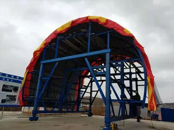
Tunnel construction projects are notoriously time-sensitive, where even a single week of delay can cascade into budget overruns and contractual penalties. Traditional formwork systems, while reliable, often require extensive on-site assembly, welding, and adjustment—eating up precious days. Gaofei has engineered a solution that addresses this bottleneck head-on: a rapid assembly tunnel formwork system that consistently delivers a 15-day reduction per project. This is not a theoretical figure—it is a documented outcome from multiple mid-to-large scale tunnel projects. This article breaks down the technical innovations, quantifiable savings, and practical implementation strategies behind this 15-day advantage, helping decision-makers evaluate whether this system aligns with their operational goals.

Understanding the Time Challenge in Tunnel Construction

Before examining the solution, it is essential to grasp where time is lost in conventional tunnel formwork processes.

Traditional Formwork Constraints

Standard tunnel formwork systems typically require:

  • Heavy steel components that demand cranes and multiple workers for each repositioning cycle.
  • Extensive bolting and welding on site, which introduces quality variability and safety risks.
  • Multiple adjustment stages to align panels, resulting in a typical cycle time of 3–5 days per pour segment.
  • Dependence on skilled labor shortages can stall progress.

These constraints mean that a 1,000-meter tunnel can easily lose 2–3 weeks purely to formwork handling inefficiencies.

How Rapid Assembly Tunnel Formwork Reduces Project Duration

Tunnel Formwork

Gaofei’s rapid assembly system re-engineers the formwork workflow by focusing on three core principles: modularity, lightweight construction, and integrated quick-connect mechanisms.

  • Pre-assembled modular panels: Panels arrive at the site as complete units with pre-drilled connections. No on-site welding is required, reducing setup time by up to 40%.
  • Hydraulic retraction and repositioning: A built-in hydraulic system allows the entire formwork carriage to roll forward within minutes, versus hours with traditional jacks and manual supports.
  • Quick-connect locking pins: Instead of dozens of bolts per joint, a single locking pin secures each panel interface, cutting assembly/disassembly labor by 60%.
  • Integrated alignment system: Laser-guided alignment eliminates the need for repeated manual measurements on each cycle.

These features combine to create a cycle time of just 1.5 days per pour segment—a 50–60% reduction compared to conventional 3–4 day cycles. Over a typical 30-segment tunnel project, this directly yields a 15-day total saving.

Click here for more details on rapid-assembly tunnel formwork that can save 15 days of construction time per project: https://www.gf-bridge-tunnel.com/a/blog/rapid-assembly-formwork.html

Achieving zero-defect tunnel linings is the gold standard in underground construction, yet many projects fall short due to inconsistencies in concrete placement, formwork stability, or curing conditions. Every void, crack, or honeycomb not only compromises structural integrity but also leads to costly rework and schedule delays. This article provides a systematic approach to eliminating defects, covering mix design, formwork technology, placement methods, and quality control protocols. By integrating proven techniques and leveraging advanced equipment such as Gaofei‘s tunnel formwork systems, contractors can consistently produce linings that meet the highest standards of durability and appearance.

Understanding the Core Requirements for Zero-Defect Tunnel Linings

Zero-defect tunnel lining demands a holistic approach that begins long before concrete is poured. The three pillars are uniform concrete quality, precise formwork geometry, and controlled placement. Without mastering these fundamentals, even the best equipment will not guarantee defect-free results.

Concrete Quality and Mix Design

The concrete mix must be optimized for workability, low shrinkage, and adequate strength gain. Key parameters include a well-graded aggregate, suitable water-cement ratio, and the use of superplasticizers to achieve high flowability without segregation. For tunnel linings, a slump flow of 600–700 mm is often recommended to ensure complete filling of the formwork cavity, especially around reinforcement and complex sections. Additionally, low-heat cement or supplementary cementitious materials like fly ash can reduce thermal cracking in thick sections.

Formwork and Pouring Techniques

Formwork must be rigid, accurately aligned, and leak-proof. Steel tunnel formwork systems, such as those provided by Gaofei, offer the necessary stiffness and dimensional repeatability to maintain lining thickness and surface finish. During pouring, concrete should be introduced from multiple points using a tremie or concrete pump to avoid cold joints. The placement rate must be controlled to prevent excessive hydrostatic pressure that could displace the formwork.

Curing and Quality Control

Immediate and continuous curing is critical. For tunnel linings, wet curing with water sprays or curing compounds should start as soon as the formwork is stripped (typically after 12–16 hours). Temperature monitoring inside the concrete can help manage thermal gradients. Non-destructive testing methods, such as ultrasonic tomography or ground-penetrating radar, can be used to verify internal density and detect hidden voids.

Common Defects in Tunnel Linings and Their Root Causes

 Tunnel Linings

Understanding why defects occur is the first step toward prevention. The most frequent issues include surface voids (bug holes), honeycombing, cracking, and delamination. Each has specific causes that can be addressed through proper technique and equipment.

Click here for more details on how to achieve zero-defect tunnel lining with every pour: https://www.gf-bridge-tunnel.com/a/blog/zero-defect-tunnel-pour.html

In tunneling and high-rise construction, safety is not merely a compliance checkbox—it is a fundamental operational metric that can determine project profitability and worker survival. Traditional formwork systems often rely on manual oversight to prevent structural failures, falling debris, and electrical threats, leaving room for human error. However, advanced tunnel formwork systems, such as those engineered by Gaofei, incorporate automated mechanisms that neutralize the three deadliest hazards on site without requiring constant operator intervention. Understanding how these systems function can help project managers make informed procurement decisions and significantly reduce liability exposure.

1. Collapse and Structural Instability

Formwork collapse remains the leading cause of fatalities in concrete construction worldwide. When manual bracing is misaligned or load distribution is uneven, the entire assembly can fail during pouring. Gaofei tunnel formwork eliminates this risk through two key automated features:

Self-Locking Hydraulic Braces

Unlike traditional systems where workers must manually tighten braces and check alignment, Gaofei tunnel formwork integrates self-locking hydraulic braces that automatically engage when the formwork reaches its correct position. Sensors monitor vertical and horizontal alignment in real time; if any deviation exceeds predefined tolerances, the system halts the pouring process and activates an alarm. This eliminates the possibility of collapse from subtle misadjustments that would otherwise go unnoticed.

Load-Balanced Panel Design

The formwork panels themselves are engineered with an internal load‑balancing structure that distributes concrete pressure uniformly across the framework. Computational fluid dynamics simulations during design ensure that no single panel bears more than its rated capacity. As a result, even if one hydraulic component fails, the remaining units automatically redistribute the load to prevent catastrophic failure. Gaofei field data indicates a 67% reduction in structural incidents across projects using this automated system compared to conventional formwork.

2. Falling Objects and Worker Injury

tunnel formwork systems

In traditional formwork operations, workers often need to climb the framework to install ties, remove panels, or reposition safety nets. Each climb introduces the risk of dropped tools, loose components, and slips. Gaofei tunnel formwork addresses these dangers through a combination of robotic handling and integrated fall protection.

Automatic Panel Retrieval and Placement

The system includes a rail‑mounted robotic carrier that retrieves and positions each formwork panel without requiring workers to physically handle heavy steel sections. This eliminates the most common source of struck‑by injuries—manual lifting and positioning—and reduces ergonomic strains that lead to costly medical leaves. The automated retrieval sequence is pre‑programmed to follow site‑specific lift plans, ensuring no panel swings unexpectedly into walkways.

Click here for more detailed information on the three major safety hazards associated with the automatic removal of tunnel formwork:https://www.gf-bridge-tunnel.com/a/blog/tunnel-formwork-safe.html

Proper installation of a slewing bearing is critical for the performance and longevity of heavy equipment such as excavators, cranes, wind turbines, and radar systems. Even a minor error during installation can lead to premature failure, costly downtime, or even safety hazards. In this guide, we highlight three of the most common yet expensive mistakes encountered during slewing bearing installation and provide expert recommendations to avoid them. Whether you are a maintenance engineer, equipment operator, or procurement specialist, understanding these pitfalls will help you maximize the service life of your bearing and reduce total cost of ownership. LYMC, a trusted manufacturer in the slewing bearing industry, emphasizes that proper installation is just as important as the quality of the bearing itself.

Mistake #1: Improper Handling and Mounting Surface Preparation

One of the most overlooked aspects of slewing bearing installation is the condition of the mounting surfaces and the handling procedures. Many failures trace back to contamination, inadequate flatness, or surface roughness.

Consequences of Poor Preparation

  • Uneven load distribution leading to localized stress concentrations and raceway deformation.
  • Premature wear of rolling elements due to foreign particles embedded in the mating surfaces.
  • Increased friction and heat generation, accelerating lubricant degradation.

How to Do It Correctly

  1. Inspect both the bearing mounting surface and the support structure for flatness. The recommended flatness tolerance is typically 0.1 mm/m (refer to LYMC installation manual for your specific model).
  2. Clean all surfaces with a lint-free cloth and approved solvent. Remove any burrs, rust, or paint residue.
  3. Apply a thin layer of anti-corrosion oil or grease on the mounting surfaces unless specified otherwise by the manufacturer.
  4. Always use proper lifting equipment – never drag the bearing across the floor. Use soft slings or lifting eyes designed for the bearing weight.
  5. Verify that the mounting bolts are of the correct grade and length. Use new bolts if recommended by LYMC.

Mistake #2: Incorrect Bolt Torque and Tightening Sequence

Even with a perfectly prepared surface, improper bolt tightening is a leading cause of slewing bearing failures. This mistake is often driven by haste or the use of inaccurate torque tools.

Why This Matters

The slewing bearing relies on a specific clamping force to maintain preload and prevent relative movement between races. Over‑tightening can distort the bearing rings, while under‑tightening can allow the bearing to shift under load, causing rapid wear.

Click here for more details on the installation guide for slewing bearings and how to avoid three costly mistakes: https://www.mcslewingbearings.com/a/news/slewing-bearing-installation-guide.html

Choosing between a single-row and a double-row slewing bearing is a critical decision that directly impacts the performance, durability, and cost-efficiency of your rotating equipment. Whether you are designing a new crane, excavator, wind turbine, or robotic arm, the wrong selection can lead to premature failure or unnecessary expense. This article provides a professional, side-by-side comparison of single-row and double-row slewing bearings, covering structural differences, load capabilities, stiffness, maintenance, and typical applications. With insights from LYMC, a leading manufacturer of precision slewing bearings, you will gain the clarity needed to make an informed choice.

Understanding the Basics: Single-Row and Double-Row Slewing Bearings

Single-Row Slewing Bearings

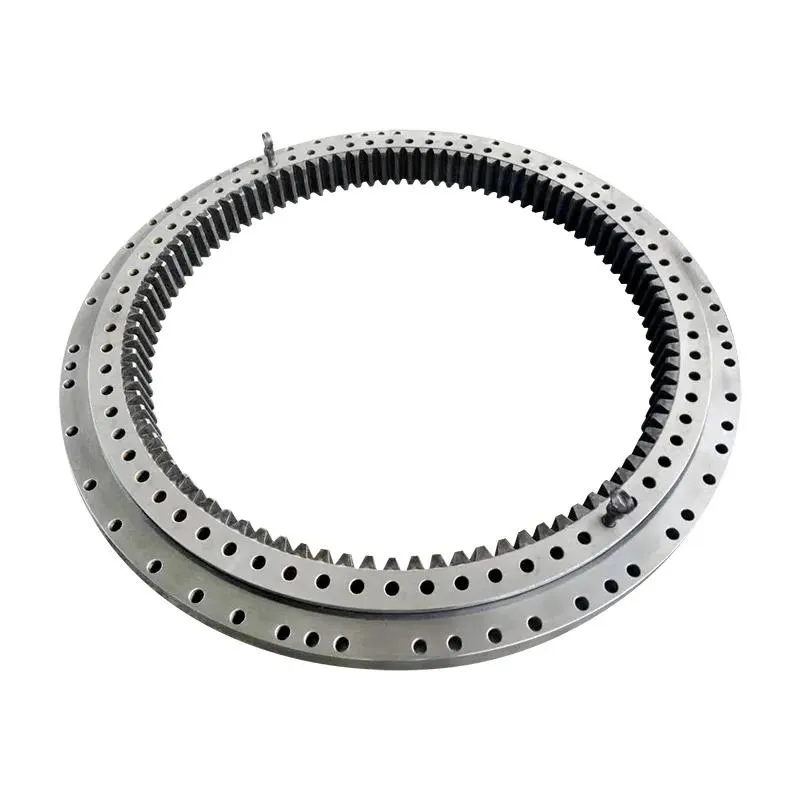
A single-row slewing bearing consists of one row of rolling elements (balls or rollers) arranged in a single raceway. This design is compact, lightweight, and cost-effective. It can handle moderate axial loads, radial loads, and tilting moments simultaneously, making it suitable for many light-to-medium duty applications. Common uses include small cranes, aerial work platforms, solar trackers, and medical equipment.

Double-Row Slewing Bearings

A double-row slewing bearing features two rows of rolling elements, usually with a larger cross-section and more robust raceways. The dual-row configuration significantly increases load capacity and stiffness, especially for tilting moments. These bearings are engineered for heavy-duty equipment such as large excavators, offshore cranes, wind turbine yaw systems, and military vehicles. They offer higher rigidity but come with increased weight, size, and cost.

Key Differences Between Single-Row and Double-Row Slewing Bearings

Slewing Bearings

Understanding the fundamental contrasts helps narrow down your options. The table below summarizes the main differences, but we will explore each aspect in detail.

  • Load Capacity: Double-row bearings can withstand significantly higher axial, radial, and moment loads due to the additional rolling elements and larger contact area.
  • Stiffness: Double-row designs exhibit 30–50% higher rigidity, reducing elastic deformation under heavy loads.
  • Size and Weight: Single-row bearings are more compact and lighter, ideal for space-constrained applications. Double-row bearings require larger mounting envelopes.
  • Cost: Single-row bearings are generally 20–40% less expensive than equivalent double-row models, both in initial purchase and replacement.
  • Maintenance and Sealing: Single-row bearings have fewer sealing points, simplifying lubrication and inspection. Double-row bearings may require more frequent maintenance due to additional raceways.

For more detailed information on how to choose between single-row and double-row slewing bearings, please click here: https://www.mcslewingbearings.com/a/news/slewing-bearing-compare.html

Slewing bearings are critical components in heavy machinery such as cranes, excavators, wind turbines, and material handling equipment, enabling smooth rotational movement under extreme loads. Despite their robust design, these bearings are susceptible to a range of failures that can lead to costly downtime, unsafe operating conditions, and premature replacement. Understanding the root causes of these failures—and implementing targeted prevention strategies—is essential for maximizing equipment reliability and total cost of ownership. This article examines the most common slewing bearing failure modes experienced across industries and provides actionable prevention guidance, with insights from LYMC, a leading manufacturer known for precision-engineered slewing bearings.

1. Material Spalling and Flaking

Spalling, also referred to as flaking or pitting, is the gradual removal of metal from the raceway surfaces or rolling elements. It is the most frequently reported failure mode in slewing bearings, often resulting in vibration, noise, and eventual seizure.

Root Causes

  • Overloading: Excessive static or dynamic loads beyond the bearing’s rated capacity cause subsurface fatigue, initiating cracks that propagate to the surface.
  • Inadequate lubrication: Insufficient or degraded grease fails to form a protective elastohydrodynamic film, leading to metal-to-metal contact and accelerated wear.
  • Contamination: Hard particles such as sand, dust, or metal debris enter the bearing raceways, acting as abrasives that induce micro-cracking.
  • Misalignment: Angular misalignment between the bearing rings concentrates stress on localized areas, promoting early spalling.

Prevention Measures

  • Strictly adhere to the manufacturer’s load ratings and avoid shock loads during operation.
  • Implement a scheduled relubrication program using high-quality grease appropriate for the operating environment (temperature, moisture, speed).
  • Use proper sealing solutions such as labyrinth seals or elastomeric lip seals to keep contaminants out. LYMC bearings feature advanced multi-lip seal designs that provide superior ingress protection.
  • Verify alignment during installation with a dial indicator or laser alignment tool; shim as needed to achieve parallelism within 0.1 mm per meter.

2. Cracked Rings or Fractured Raceways

Slewing bearings

Cracking—whether in the inner ring, outer ring, or rolling elements—is a catastrophic failure that often results in immediate equipment stoppage and potential safety hazards.

Root Causes

  • Brinelling: High static impact loads (e.g., during transport or improper lifting) create indentations that act as stress raisers, leading to ring fracture.
  • Thermal stress: Rapid temperature changes or uneven heating (e.g., from welding nearby) can cause differential expansion and cracking.
  • Hydrogen embrittlement: In corrosive environments, hydrogen atoms diffuse into the steel, reducing toughness and causing sudden fracture.
  • Material defects: Inclusions, porosity, or improper heat treatment in inferior bearings create weak points.

For more detailed information on common slewing bearing failures and their prevention, please click here: https://www.mcslewingbearings.com/a/news/slewing-bearing-failures.html