glass tempering furnace is a specialized piece of equipment used in the glass manufacturing industry to temper glass, making it stronger and safer than untreated glass through a specific process. The core of the tempering process lies in heating the glass to a high temperature close to the softening point and then cooling it rapidly, thus creating a pre-stress within the glass, which can significantly improve the strength and durability of the glass. The technical parameters of the glass tempering furnace, like the scales on a precision instrument, directly determine the final quality of the tempered glass, and they are inextricably linked.
To this end, we will be from five key dimensions, the glass tempering furnace technical parameters for in-depth analysis:

1.temperature setting:

Temperature control during the tempering process is critical. Heating temperature needs to be set precisely to ensure that the glass can be uniformly heated to close to the softening point. At the same time, the temperature stage is also critical, it helps to eliminate the temperature gradient within the glass, to ensure uniformity of the tempering effect. The cooling temperature determines the cooling rate, which in turn affects the size and distribution of the prestress. Different types of glass require different temperature settings due to differences in composition, thickness and thermal conductivity. Therefore, in practice, the temperature parameters need to be flexibly adjusted according to the specific type and specification of the glass.

2. time settings:

Time parameters also have an important impact on the tempering effect. Heating time needs to be long enough to ensure that the glass can be fully heated; heat time should be determined according to the thickness of the glass and the heating rate to ensure a uniform distribution of temperature; cooling time needs to be rapid and stable to ensure that the pre-stress can be correctly formed. Different types of glass require different time settings due to their different thermal response characteristics. Therefore, in practice, the heating, heating and cooling times need to be accurately controlled to obtain the best tempering effect.

 glass tempering furnace

3.Furnace chamber pressure and fuel-air ratio setting:

Furnace chamber pressure has a direct impact on the heating efficiency and quality of glass. Appropriate chamber pressure helps to speed up the heating rate and improve the heating efficiency. At the same time, the furnace chamber pressure also needs to be matched with the cooling system to ensure that the glass in the cooling process can quickly cool down, the formation of a stable pre-stress. Fuel-air ratio is related to the completeness of combustion and the efficiency of energy utilization. Reasonable fuel-air ratio helps to reduce the pollutants produced by combustion and improve the efficiency of energy utilization. In practice, the furnace chamber pressure and fuel-air ratio need to be flexibly adjusted according to the type of glass, specifications and production requirements.
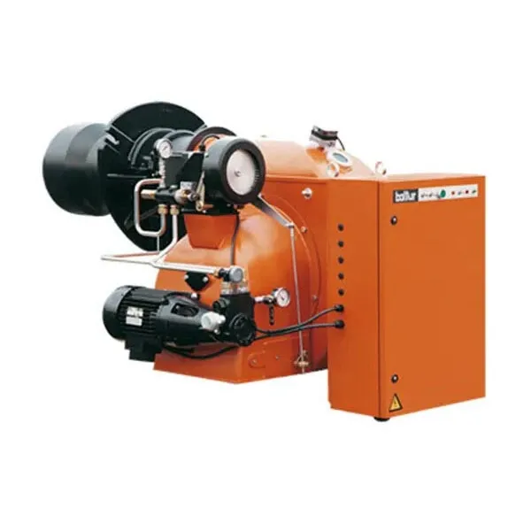
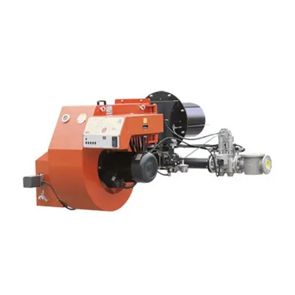
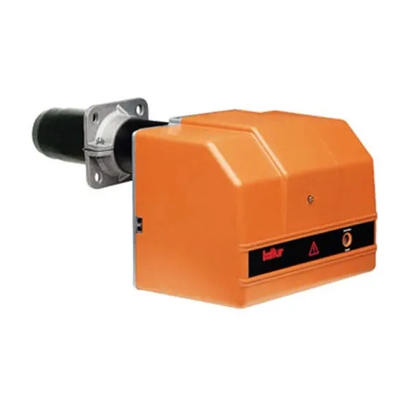
Furnace pressure is generally set to 0.2-0.6MPa, in order to ensure that the heating rate and heating efficiency of the balance; fuel – air ratio is usually set to 1.05-1.2, in order to meet the needs of the complete combustion; combustion air volume is generally 16,000-32,000Nm³/h, in order to ensure that the stability of the gas flow in the furnace chamber and uniformity.

More detailed information about the tempered glass furnace technical parameters can be found by visiting:https://www.shencglass.com/en/a/news/technical-parameters-of-glass-tempering-furnace.html

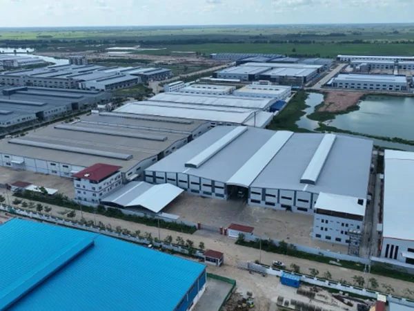
structural steel factory is a facility dedicated to the fabrication, processing, and assembly of structural steel components used in construction, manufacturing, and infrastructure projects. These factories play a critical role in providing the steel elements that form the backbone of buildings, bridges, industrial facilities, and other structures.

Designing a structural steel factory requires careful planning to ensure efficient operations, safety, and compliance with regulations. Below is an outline of the key considerations and design principles for a structural steel factory.

Structural Steel Factory Design Process

structural steel factory

1. Feasibility Study and Planning

Site Selection:

Analyze the location for accessibility, land size, soil conditions, and proximity to raw material sources and markets.

Requirements Definition:

Determine production capacity, equipment layout, storage needs, and future expansion plans.

Budgeting:

Establish a budget covering construction, equipment, utilities, and contingencies.

2. Conceptual Design

Factory Layout:

Define the flow of materials and operations (e.g., receiving, processing, assembly, storage, and shipping).

Optimize space utilization and minimize material handling.

Structural Requirements:

Consider the type of structural steel to be processed and the machinery loads.

Utilities and Support Systems:

Plan for power supply, ventilation, water, and waste management systems.

3. Detailed Design

A. Architectural Design

Building Dimensions:

Define clear spans, ceiling height, and column placement to accommodate equipment and workflows.

Aesthetic and Functional Elements:

Design facades, access points, and office spaces.

B. Structural Design

Framework Design:

Use steel beams, columns, trusses, and purlins for the main structure.

Load Analysis:

Account for dead loads (self-weight), live loads (machinery, workers), wind loads, seismic loads, and snow loads (if applicable).

More detailed information about the design process of the steel structure factory can be found by visiting: https://www.meichensteel.com/a/news/structural-steel-factory-design-process.html

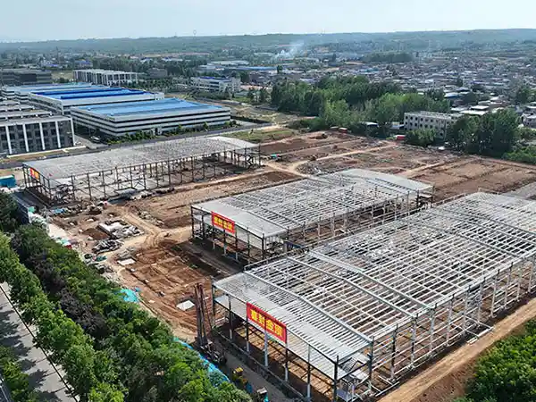
Installing a steel structure workshop involves the same principles as any steel structure but tailored to the specific requirements of a workshop, including size, layout, and purpose. Here’s a step-by-step guide to installing a steel structure workshop.

Steel Structure workshop Installation Guide

steel structure workshop

1. Planning and Design

Structural Design: Work with an architect or structural engineer to design the workshop. Ensure the design accounts for:

Dimensions (height, width, length)

Load-bearing requirements

Ventilation, insulation, and lighting needs

Specific features (e.g., mezzanines, overhead cranes)

Permits and Approvals: Obtain necessary building permits and approvals from local authorities.

2. Site Preparation

Clear the Site: Remove debris, vegetation, or obstacles from the construction area.

Foundation Work:

Excavate and lay the foundation as per design specifications.

Use reinforced concrete for the foundation to provide a stable base for the steel structure.

Ensure anchor bolts are placed accurately according to the structural plans.

3. Steel Frame Assembly

Erect Steel Columns: Start by positioning vertical steel columns at their designated spots using cranes or lifting equipment. Secure them to the anchor bolts in the foundation.

steel structure workshop

Install Roof Beams and Trusses: Connect the horizontal beams and roof trusses to the vertical columns.

Temporary Bracing: Use temporary bracing to stabilize the frame during installation.

More detailed information about steel structure workshop installation can be found by clicking visit: https://www.meichensteel.com/a/news/steel-structure-workshop-installation.html

steel structure design plan serves as a comprehensive roadmap for designing, analyzing, and constructing a steel structure. It involves detailing the objectives, requirements, design processes, and standards to ensure the structure meets functional, aesthetic, and safety goals.

Steel Structure Design Plan

Steel Structure

1. Project Definition and Scope

Objective:

Define the purpose of the structure (e.g., industrial facility, warehouse, office building, bridge, etc.).

Project Specifications:

Determine dimensions, capacity, load requirements, and intended lifespan.

Budget and Timeline:

Establish cost constraints and project deadlines.

2. Preliminary Design

Site Survey:

Conduct soil investigations to determine foundation requirements.

Analyze environmental factors (e.g., wind, snow, seismic conditions).

Conceptual Design:

Develop a basic layout, including the building’s shape, span, height, and layout.

Plan for usage of space, access points, and expansions.

3. Structural Analysis

Load Considerations:

Dead Loads: Self-weight of structural elements (beams, columns, roofing).

Live Loads: Movable loads (machinery, people, vehicles).

Environmental Loads: Wind, seismic activity, snow, and temperature variations.

Load Path Analysis:

Ensure loads are transferred safely to the foundation.

4. Design of Structural Components

A. Primary Components

Columns:

Design for axial loads, bending moments, and lateral forces.

Choose cross-sections (e.g., H-beams, box sections) based on strength and stability.

Beams:

Calculate bending stresses and shear forces.

Optimize spans and connections.

Trusses (if applicable):

Design for large spans, optimizing material usage with tension/compression members.

More detailed information about steel structure design can be found by visiting: https://www.meichensteel.com/a/news/steel-structure-design-plan.html

A slewing bearing consists of several key components designed to handle axial, radial, and moment loads simultaneously. Here are the primary components:

1. Rings (Inner and Outer Rings)

Inner Ring:

Mounted to the stationary or rotating part of the equipment.

Includes gear teeth in geared slewing bearings for power transmission.

Outer Ring:

Supports the opposite component (stationary or rotating).

May also feature gear teeth in external-geared designs.

Function:

Provide the raceways for rolling elements and structural stability.

2. Rolling Elements

Balls or Rollers:

Balls: Used in ball slewing bearings for lower friction and moderate loads.

Rollers: Used in roller slewing bearings for higher load capacities.

Configuration:

Single-row or multi-row (e.g., double-row balls, triple-row rollers).

Crossed roller arrangements for precision and moment load handling.

3. Spacer or Cage

Purpose:

Keeps the rolling elements evenly spaced along the raceway.

Prevents direct contact between rolling elements, reducing wear and friction.

Materials:

Usually made of nylon, steel, or brass, depending on the operating conditions.

slewing bearing

4. Seals

Function:

Protect the bearing’s internal components from contamination (dust, dirt, moisture).

Retain lubrication within the bearing.

Materials:

Made of rubber or other durable, flexible materials.

5. Gear Teeth (Optional)

External Gear:

Gear teeth located on the outer ring.

Internal Gear:

Gear teeth located on the inner ring.

Purpose:

Allow the bearing to transmit rotational motion from a drive mechanism, such as a pinion gear.

6. Raceways

Description:

Grooved tracks on the inner and outer rings where rolling elements move.

Function:

Provide the contact surfaces for rolling elements, supporting loads and facilitating smooth rotation.

More detailed information about the composition of slewing bearings can be found by clicking on the visit to: https://www.mcslewingbearings.com/en/a/news/slewing-bearing-components.html

Selecting the appropriate slewing bearing involves several factors to ensure it meets the application’s requirements for load capacity, operational conditions, and longevity. Below is a systematic guide for selecting slewing bearings.

Slewing bearing selection

slewing bearing

1. Understand the Application Requirements

A. Load Conditions

Axial Load: Force acting perpendicular to the bearing’s axis.

Radial Load: Force acting along the bearing’s axis.

Moment Load: Torque or tilting forces acting on the bearing.

Consider whether the load is constant, variable, or shock-inducing.

B. Operational Parameters

Rotational Speed: Maximum and average speed the bearing must handle.

Duty Cycle: Frequency and duration of operation (e.g., continuous, intermittent).

Precision: Required accuracy in positioning or rotation.

C. Environmental Conditions

Temperature: Minimum and maximum operating temperatures.

Contaminants: Dust, moisture, or corrosive environments that may affect the bearing.

Lubrication: Compatibility with the lubrication system (grease, oil).

D. Mounting and Space Constraints

Dimensions: Inner and outer diameter, height, and weight limits.

Mounting: Bolt hole patterns and flange compatibility.

2. Determine the Bearing Type

Slewing bearings come in various types, each suited to specific applications:

Single-row Ball Bearings:

Suitable for light to moderate axial, radial, and moment loads.

More detailed information about slewing bearing selection can be found by clicking visit: https://www.mcslewingbearings.com/en/a/news/how-to-select-slewing-bearings.html

Slewing bearings, also known as slewing rings, are specialized bearings designed to support axial, radial, and moment loads, typically used in applications like cranes, wind turbines, and excavators. They are classified based on their structural design, the number of rolling elements, and the type of load they are designed to handle.

Slewing Bearing Types

Slewing bearings

1. Single-Row Four-Point Contact Ball Bearings

Description: These bearings have a single row of balls that make four points of contact with the raceways.

Features:

Capable of handling axial, radial, and moment loads simultaneously.

Compact design.

Moderate load-carrying capacity.

Applications: Cranes, excavators, turntables, and light-duty equipment.

2. Single-Row Crossed Roller Bearings

Description: This type has a single row of cylindrical rollers arranged in a crisscross pattern, alternating at 90° angles.

Features:

High precision and rigidity.

Excellent for applications requiring minimal deflection.

Can handle higher moment loads compared to ball bearings of similar size.

Applications: Robotics, medical equipment, and precision machinery.

3. Double-Row Ball Bearings

Description: These bearings have two rows of balls, typically separated by a spacer.

Features:

Higher load-carrying capacity compared to single-row designs.

Handles heavy axial and radial loads but limited moment load capability.

Applications: Wind turbines, heavy-duty cranes, and construction machinery.

4. Three-Row Roller Bearings

Description: These bearings consist of three separate rows of rollers, each designed to carry a specific type of load (radial, axial, or moment).

Features:

Extremely high load-carrying capacity.

Larger size and heavier weight compared to other types.

Applications: Large excavators, ship cranes, and heavy-duty rotating machinery.

More detailed information about slewing bearing types can be found by clicking visit: https://www.mcslewingbearings.com/en/a/news/slewing-bearing-types.html

A white mist or haze appearing on tempered glass is a common quality issue that can result from various factors during the tempering process. It is often due to contamination, improper heating, or cooling issues. Here’s how to identify the cause and fix it.

Glass Tempering White Mist Solutions

Glass Tempering Furnace

1. Causes of White Mist on Tempered Glass

A. Contamination Before Heating

Dirty Glass Surface: Residual oils, dirt, or cleaning chemicals can burn onto the glass surface during heating.

Improper Washing: Insufficient rinsing in the washing process may leave detergent or hard water residues.

B. Furnace Conditions

Uneven Heating: Temperature inconsistencies in the heating chamber can cause uneven surface stress, leading to haze.

Excessive Heating: Overheating can burn contaminants or create visible distortions.

C. Cooling (Quenching) Issues

Uneven Air Flow: Non-uniform cooling due to blocked or misaligned air nozzles can leave areas of different stress levels, causing haze.

Improper Quenching Pressure: Low or excessively high air pressure during cooling can affect the surface finish.

D. Poor Quality Glass

Low-Quality Raw Glass: Inherent impurities in the glass may become visible after tempering.

2. Solutions to Fix White Mist

A. Pre-Heating Cleaning Process

Improve Washing:

Use a high-quality glass washing machine with effective cleaning and rinsing stages.

Use deionized water to prevent hard water stains.

Inspect for Contaminants:

Ensure all glass is inspected for visible dirt, grease, or residues before loading.

Drying:

Ensure glass is completely dried to avoid water spots entering the furnace.

B. Furnace Adjustments

Temperature Control:

More detailed information about the glass tempering furnace white mist problem can be clicked to visit: https://www.shencglass.com/en/a/news/glass-tempered-white-mist.html

glass tempering furnace is a specialized machine used to strengthen glass by heating and rapid cooling, creating tempered glass that is more durable and safer than regular annealed glass. The process involves precise control of temperature and cooling to induce compressive stresses on the glass surface. Here’s how it works:

1. Pre-Processing

Before entering the tempering furnace:

Cutting and Edging:

Glass sheets are cut to the desired size and edges are smoothed to prevent breakage during tempering.

Washing:

Glass is thoroughly cleaned to remove dirt and contaminants that might affect the heating and cooling process.

Inspection:

Glass is checked for defects like chips or cracks that could cause failure during tempering.

2. Heating Stage

Loading:

Glass sheets are loaded onto a conveyor system or rollers that transport them through the furnace.

Heating Chamber:

Glass is heated to a temperature of approximately 620–700°C (1148–1292°F), depending on the type and thickness of the glass.

Uniform Heating:

Electric or gas-fired heaters provide consistent and uniform heat.

Convection and/or radiant heating ensures the glass reaches its softening point without deforming.

Temperature Control:

Sensors monitor the glass temperature to avoid overheating or uneven heating.

3. Soaking Period

Thermal Equalization:

Glass is held at the target temperature for a short period to ensure the entire sheet is uniformly heated.

Proper soaking prevents stress imbalances during the cooling phase.

4. Rapid Cooling (Quenching)

Cooling System:

The heated glass exits the furnace into the quenching section, where high-velocity air jets cool it rapidly.

Air Nozzles:

Jets of cool air are blown onto both surfaces of the glass simultaneously.

Stress Induction:

The rapid cooling causes the outer surfaces of the glass to contract quickly, creating a layer of compressive stress.

The interior cools more slowly, resulting in tensile stress at the core.

Controlled Cooling:

The process is carefully controlled to avoid cracking or deformation.

5. Unloading and Inspection

More detailed information about the working principle of glass tempering furnace can click to visit: https://www.shencglass.com/en/a/news/glass-tempering-furnace-working-principle.html

The glass tempering process is a method used to strengthen glass, making it much more resistant to impact, thermal stress, and breakage. The process involves heating the glass to a high temperature and then rapidly cooling it to create internal stress, which increases the glass’s strength.

Steps in the Glass Tempering Process

Glass tempering furnace

Cutting and Shaping

The glass is first cut and shaped to the desired dimensions. It’s important that all edges are smooth because sharp edges can result in weaknesses during the tempering process.

Heating

The glass is heated to a temperature between 600°C (1112°F) and 650°C (1202°F). At this stage, the glass becomes soft and malleable, but it doesn’t melt.

Quenching (Rapid Cooling)

After the glass reaches the desired temperature, it is quickly cooled using high-pressure air jets. The cooling happens very quickly, typically within 1 to 2 minutes.

Outer Surface Cooling: The outer surfaces of the glass cool down rapidly, solidifying quickly.

Inner Core: The inner part of the glass cools more slowly, creating a compression layer on the outer surface and tension inside the glass.

Strengthening

This combination of compressed outer layers and tension inside gives tempered glass its characteristic strength. The compressive stress makes the glass much more resistant to cracks and breakage.

Edge Inspection and Quality Control

After tempering, the glass is checked for quality. If the glass has any defects, it may need to be discarded or reprocessed. Additionally, tempered glass cannot be cut or altered after tempering without compromising its strength, so this inspection step is important before final installation.

Characteristics of Tempered Glass

Glass tempering furnace

Strength: Tempered glass is approximately 4 to 5 times stronger than regular, annealed glass of the same thickness.

Safety: When tempered glass breaks, it fractures into small, blunt pieces instead of sharp shards, reducing the risk of injury.

Thermal Resistance: Tempered glass is more resistant to thermal stress and can withstand temperature differences up to about 200°F (93°C) without breaking.

For more detailed information on the glass tempering process, please visit: https://www.shencglass.com/en/a/news/glass-tempering-process.html