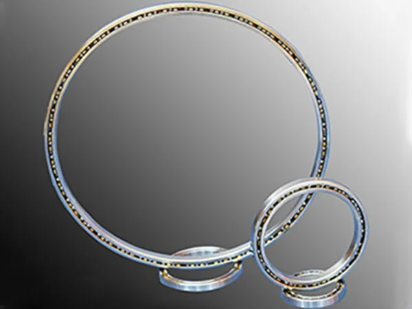
The sizes of tractor friction discs can vary depending on the make and model of the tractor, as well as the specific application for which they are designed. Friction discs are commonly used in the tractor’s clutch system to engage and disengage power transmission between the engine and the transmission. These discs are crucial components for smooth operation and control of the tractor.

While specific sizes can differ, here are some general points about tractor friction discs and their applications:

Sizes

  • Diameter: The diameter of a friction disc is a critical dimension. It is typically measured in inches or millimeters. Common diameters for tractor friction discs can range from a few inches to larger sizes, depending on the tractor’s horsepower and design.
  • Thickness: The thickness of friction discs is another important dimension. It is measured in millimeters or inches. Thicker discs are often used in heavy-duty applications.

Materials

  • Friction discs are typically made from materials that provide good frictional properties and durability. Common materials include organic compounds, metal, or a combination of materials.

Applications

  • Clutch System: Friction discs are a crucial part of the tractor’s clutch system. When the clutch is engaged, these discs create friction to transmit power from the engine to the transmission. When the clutch is disengaged, the discs separate, interrupting the power transmission.

For more detailed information about tractor friction disc applications, please click here: https://www.syclutch.com/news/tractor-friction-plate-application.html

linear vibrating screen is a mechanical device that utilizes vibrating motors to impart motion to the screen deck. This motion is used to separate materials based on size.

Linear vibrating screen components

Double banana sieve

Screen Frame: The screen frame is the structural backbone of the vibrating screen. It supports the screen mesh and other components. It may be made of steel or other materials to provide the necessary strength and rigidity.

Screen Mesh: The screen mesh is the material that covers the screen frame and separates the particles based on size. It can be made of various materials, such as woven wire cloth, perforated metal, or synthetic materials. The choice of mesh type and size depends on the application and the size of the particles being separated.

Vibrating Motors: These are the driving force behind the linear motion of the screen. Vibrating motors are usually mounted on the sides of the screen frame and generate the vibrations needed for material separation. The number and placement of vibrating motors can vary depending on the size and design of the vibrating screen.

High Frequency Dehydration Vibrating Screen

Support Springs: Support springs are used to absorb the dynamic forces generated by the vibrating motors. They help to isolate the vibrating screen from the surrounding structure and minimize vibrations transmitted to the supporting structure.

Drive Unit: The drive unit includes the motor and associated components responsible for generating the linear motion. It converts the rotary motion of the motor into the linear motion required for the vibrating screen.

For more detailed information about the composition of linear vibrating screens, please click here: https://www.hsd-industry.com/news/linear-vibrating-screen-composition/

multiprocess welder, also known as a multi-process welder or multi-purpose welder, is a welding machine that is capable of performing different types of welding processes using various welding techniques. These machines are versatile and designed to handle different welding applications, offering flexibility to welders who may need to work on various projects with diverse materials.

The main welding processes that a multiprocess welder can typically handle include

Multiprocess Welders

Shielded Metal Arc Welding (SMAW): Also known as stick welding, this process uses a flux-coated electrode to create an arc between the electrode and the workpiece.

Gas Metal Arc Welding (GMAW): Commonly known as MIG (Metal Inert Gas) or MAG (Metal Active Gas) welding, this process uses a consumable wire electrode and a shielding gas to protect the weld.

Flux-Cored Arc Welding (FCAW): Similar to MIG welding, FCAW uses a tubular wire filled with flux to create a shielded arc.

Gas Tungsten Arc Welding (GTAW): Also known as TIG (Tungsten Inert Gas) welding, this process uses a non-consumable tungsten electrode and a shielding gas.

Submerged Arc Welding (SAW): This process involves the formation of an arc between a continuously fed wire electrode and the workpiece, while a layer of granular flux covers the welding zone.

The advantage of a multiprocess welder is that it allows a welder to switch between different welding processes without needing separate machines. This can be particularly useful when working on projects that require different welding techniques or when dealing with a variety of materials.

Multiprocess Welders Features

Multiprocess Welders

Multi-Process Capabilities

Stick Welding (SMAW): Ideal for welding steel, stainless steel, and cast iron.

MIG Welding (GMAW): Suitable for welding a variety of materials, especially metals like aluminum and stainless steel.

TIG Welding (GTAW): Offers precise and clean welds on materials like stainless steel, aluminum, and exotic alloys.

More detailed information about what a multi-process welder is can be found here: https://www.bota-weld.com/en/a/news/what-is-multiprocess-welders.html

Welding accessories are tools and equipment that complement the primary welding equipment and ensure the safety and efficiency of the welding process.

Welding accessories types

Welding Helmet: Protects the welder’s eyes and face from sparks, heat, and UV radiation. Auto-darkening helmets are popular for their ability to automatically adjust the shade of the lens.

Welding Gloves: Made from heat-resistant materials, welding gloves protect the hands from sparks, heat, and molten metal. They are essential for the welder’s safety.

Welding Jacket or Apron: Provides additional protection for the upper body, preventing burns and sparks from reaching the skin.

welding accessories

Welding Sleeves: These are worn on the arms to protect against sparks and UV radiation. They can be separate sleeves or integrated into a welding jacket.

Welding Boots: Heat-resistant and steel-toed boots protect the feet from sparks and heavy falling objects.

Welding Curtain or Screen: Used to create a barrier or partition in the welding area, protecting others from welding sparks and glare.

Welding Table: A stable and heat-resistant surface for placing the workpiece during welding. It often includes clamps or fixtures to hold the workpiece in place.

Chipping Hammer and Wire Brush: Used for removing slag and spatter from the welded area after the welding process is complete.

More detailed information about common types of welding accessories can be found here: https://www.bota-weld.com/en/a/news/welding-accessories-types.html

welding positioner is a mechanical device used in welding processes to position workpieces at a specific angle or orientation, making it easier for welders to access the joints and create high-quality welds. These devices are particularly beneficial for welding cylindrical or round components, as well as larger and heavier workpieces. A welding positioner is a piece of equipment that assists in the welding process by manipulating the orientation of the workpiece.

Welding positioner instruction manual

1. Safety Precautions

  • Before starting any work, ensure that you are familiar with the safety guidelines and procedures outlined in the equipment manual.
  • Wear appropriate personal protective equipment (PPE) such as welding helmets, gloves, and safety glasses.

2. Familiarize Yourself with the Positioner

  • Read the manufacturer’s manual for the specific welding positioner you are using.
  • Understand the controls, features, and specifications of the positioner.

3. Set Up the Positioner

  • Place the workpiece securely on the positioner’s table or chuck, ensuring it is centered and balanced.
  • Adjust the positioner’s settings such as rotation speed, tilt angle, and height according to your welding requirements.

4. Power On

  • Turn on the welding positioner, following the manufacturer’s instructions for startup.

5. Align the Workpiece

  • Use the positioner’s controls to align the workpiece to the desired welding position. This may involve rotation, tilting, or a combination of both.

6. Welding Preparation

  • Set up your welding machine and ensure it is in good working condition.
  • Check the welding parameters, such as voltage, current, and wire speed, and adjust them as needed for the specific welding job.

For more detailed information about the welding positioner instruction manual, please click to visit: https://www.bota-weld.com/en/a/news/welding-positioner-manual.html

ball press machine, also known as a briquette press or pellet press, is a type of mechanical equipment that presses powdery or granular materials into spherical or cylindrical shapes. These machines are often used to create briquettes or pellets for various applications, including fuel production, metallurgy, chemical processing, and more. There are different types of ball press machines, each designed for specific materials and purposes.

Ball Press Machine Type

ball press machine

Roller Type Ball Press Machine

This type of ball press machine uses two counter-rotating rollers to compact the material into the desired shape. The material is fed between the rollers, and the pressure applied by the rollers forms the material into balls or other shapes.

Hydraulic Ball Press Machine

Hydraulic ball press machines use hydraulic cylinders to apply pressure to the material, compacting it into the desired form. These machines are capable of exerting high pressure, making them suitable for processing materials that require intense compression.

Mechanical Ball Press Machine

Mechanical ball press machines utilize mechanical systems, such as gears and cams, to generate the force needed to press the material into shape. These machines may have a simpler design compared to hydraulic systems.

Screw Type Ball Press Machine

Screw press machines use a screw mechanism to compact materials. The material is fed into a chamber, and as the screw rotates, it pushes the material forward, applying pressure and forming it into the desired shape.

Piston Type Ball Press Machine

Piston press machines use a piston to apply pressure to the material. The piston is typically driven by a hydraulic or mechanical system, forcing the material into a specific mold or die to create the desired shape.

Tablet Press Machine

While not exclusively for ball-shaped products, tablet press machines can be adapted to produce small cylindrical or ball-shaped tablets. These machines are often used in pharmaceutical and chemical industries for tablet and pellet production.

For more detailed information about how much a briquetting machine costs, please click here: https://www.zymining.com/en/a/news/ball-press-machine-cost.html

briquetting machine, also known as a briquette press or briquette maker, is a device that uses pressure to turn various forms of loose raw materials, such as biomass, wood shavings, sawdust, and agricultural residues, into high-density, compacted, and consistent-shaped briquettes. These briquettes can serve as a renewable and efficient energy source or as a raw material for various industrial processes.

For more details about the briquetting machine meaning, please visit:Briquetting Machine meaning, use, price, picture

briquetting machine

Briquetting Machine Type

Screw Extruder Briquetting Machines:

Working Principle: These machines use a screw to compress the material through a tapered die.

Hydraulic Briquetting Machines:

Working Principle: Hydraulic systems generate high pressure to compress materials in a hydraulic cylinder.

Mechanical Press Briquetting Machines:

Working Principle: Operate using a mechanical eccentric action to compress materials.

Roller Press Briquetting Machines:

Working Principle: Two counter-rotating rollers compact the material into briquettes.

Piston Press Briquetting Machines:

Working Principle: A reciprocating piston compresses the material in a closed chamber.

Screw Press Briquetting Machines:

Working Principle: Similar to screw extruders, these machines use a screw to push the material through a die.

Punching Briquetting Machines:

Working Principle: Use a punching mechanism to compact the material in a closed die.

Heat Press Briquetting Machines:

Working Principle: Utilize heat to soften the material before compacting it.

Briquetting process

briquetting machine

Material Preparation:

Raw Material Selection: Choose appropriate raw materials such as biomass residues (sawdust, crop straw, etc.), industrial by-products, or other suitable materials.

Size Reduction: Grind or chop the raw materials to reduce their size, facilitating the briquetting process.

Drying (Optional):

Moisture Content Reduction: If the raw materials contain excess moisture, drying may be necessary to achieve the desired moisture content. This step improves the efficiency of the briquetting process.

For more detailed information on how to choose a briquetting machine, please click here: https://www.zymining.com/en/a/news/briquetting-machine-choose.html

compound crusher is a type of crusher that combines multiple functions into one unit. It is commonly used in the crushing production line for various hard and brittle materials, such as rock, ore, blockages, and building aggregates. The compound crusher typically includes a combination of crushers, screens, conveyors, and other equipment to facilitate the crushing process.

The design of a compound crusher allows it to perform multiple stages of crushing within a single machine. This can include primary, secondary, and even tertiary crushing processes. The compound crusher is often used in the production of artificial sand and is suitable for processing materials with high moisture content and other challenging characteristics.

One common type of compound crusher is the vertical shaft impact crusher (VSI), which uses a high-speed rotor to throw materials against the crushing chamber’s walls, breaking them into smaller pieces. Other designs may involve combinations of different types of crushers to achieve the desired crushing outcomes.

Compound crushers are employed in various industries, including mining, construction, and aggregate production, where the goal is to produce a well-graded and shaped final product efficiently.

Compound Crusher Features

compound crusher

High Crushing Efficiency: The compound crusher combines the advantages of the hammer crusher and the impact crusher. It has high crushing efficiency and is capable of crushing large materials into smaller particles.

Adjustable Discharge Size: The discharge size of the compound crusher can be adjusted by changing the gap between the impact plate and the rotor. This flexibility allows for the production of various sizes of crushed materials.

Low Maintenance: The design of the compound crusher is relatively simple, resulting in low maintenance requirements. This makes it a cost-effective option for many industries.

Wide Range of Applications: Compound crushers are suitable for crushing various materials, including coal, clinker, gypsum, limestone, and other materials with medium to high hardness.

Compound Crusher Components

compound crusher

Main Frame: The main frame provides structural support for the entire crusher.

Rotor: The rotor is the main working component of the compound crusher. It is equipped with a series of hammers or impact plates that strike the material during the crushing process.

Impact Plate: The impact plate is a crucial component that absorbs the impact energy generated during the crushing process. It plays a role in breaking down the materials into smaller particles.

For more detailed information about the compound crusher, please click here: https://www.zymining.com/en/a/news/introduction-to-compound-crusher.html

Rotary table bearings, also known as slewing bearings or turntable bearings, are specialized bearings designed to support axial, radial, and moment loads while allowing smooth rotation. These bearings are commonly used in applications where there is a need for a rotating platform or structure, such as in cranes, excavators, turntables, robotics, and other heavy machinery.

Rotary Table Bearings Features

Rotary table bearings

Single Row or Double Row:

Rotary table bearings can be single-row or double-row designs. Single-row bearings are suitable for applications with light to moderate loads, while double-row bearings provide increased load-carrying capacity.

Gear Options:

Many rotary table bearings come with gear teeth on the outer or inner ring, allowing for smooth rotation when coupled with a pinion or gear motor. This design is common in applications where controlled and precise rotation is required.

Internal Gear, External Gear, or Gearless:

Internal gear bearings have gear teeth on the inner ring, external gear bearings have teeth on the outer ring, and gearless bearings lack gear teeth altogether. The choice depends on the specific application requirements.

Sealing and Lubrication:

Rotary table bearings are often designed to be sealed to prevent contaminants from entering and to retain lubrication. Proper sealing and lubrication are crucial for the longevity and performance of the bearing.

Mounting Holes:

Some rotary table bearings come with pre-drilled mounting holes, making it easier to attach the bearing to the surrounding structure. This feature simplifies the installation process.

High Load Capacity:

Rotary table bearings are engineered to handle axial, radial, and moment loads simultaneously. This makes them suitable for applications where heavy loads and moments are present.

For more detailed information about the precautions for purchasing turntable bearings, please click here: https://www.boyingbearing.com/en/a/news/things-to-note-when-purchasing-rotary-table-bearings.html

Thin-walled bearings are designed with thin cross-sections relative to their diameter. They are used in applications where space is limited and the requirement is for reduced weight and friction. There are various types of thin-walled bearings, and their sizes can vary depending on the specific design and application.

Thin-walled bearings types

Deep Groove Ball Bearings

Sizes: The sizes can vary widely, ranging from small bearings with an inner diameter of a few millimeters to larger bearings with several hundred millimeters in diameter.

Angular Contact Ball Bearings

Sizes: Angular contact thin-walled bearings come in various sizes, catering to different load and speed requirements. The dimensions typically include inner and outer diameters, width, and contact angle.

Four-Point Contact Ball Bearings

Sizes: These bearings are designed to handle both radial and axial loads. The sizes can range from relatively small to larger diameters, depending on the specific application.

Cylindrical Roller Bearings

Sizes: Cylindrical roller bearings have various sizes, including inner and outer diameters, width, and different configurations such as single-row, double-row, or multi-row designs.

Tapered Roller Bearings

Sizes: Tapered roller bearings have varying sizes based on factors like the cone and cup dimensions, which include inner and outer diameters, width, and cone angle.

For more detailed information about thin-wall bearing types, please click here:https://www.boyingbearing.com/en/a/news/thin-wall-bearing-types.html