Choosing the appropriate motor power for a tunnel lining trolley is crucial for efficient and safe operation. It involves considering various factors related to the trolley’s function, the tunnel’s characteristics, and the concrete lining process.

Tunnel Lining Trolley Motor Power Selection

tunnel lining trolley

1. Functions of the Tunnel Lining Trolley and Associated Loads:

tunnel lining trolley typically performs several tasks, each requiring specific power:

Traveling/Movement: This is the primary function. The motor needs to overcome:

Rolling resistance: Friction between the wheels and the tracks.

Grade resistance: If the tunnel has an incline (crawling ability).

Acceleration torque: The force needed to start and increase the speed of the trolley.

Total weight of the trolley: This includes the steel formwork, hydraulic system, concrete if present during movement (though usually it’s poured after positioning), and any auxiliary equipment or personnel.

Short-distance movement: For precise positioning, motors need to provide accurate control.

Hydraulic System Operation: Most modern lining trolleys use hydraulic cylinders for various operations:

Lifting and lowering the formwork: This involves overcoming the weight of the formwork and the concrete pressure during pouring.

Opening and closing side templates: For demolding and adjustment.

Horizontal and vertical adjustments: For precise alignment.

Vibrating concrete: Some trolleys have attached vibrators to ensure proper concrete compaction. The hydraulic pump motor needs sufficient power to drive these cylinders and vibrators.

Auxiliary Functions:

Lighting: For visibility within the tunnel.

Control systems: Power for the electrical and electronic components.

2. Key Factors Influencing Motor Power Selection:

tunnel lining trolley

Trolley Specifications:

Length and weight of the trolley: Longer and heavier trolleys require more power for movement and lifting.

Maximum lining length per unit: This indicates the scale of the operation.

More detailed information about how to choose the power of tunnel lining trolley motor can be clicked to visit: https://www.gf-bridge-tunnel.com/a/blog/tunnel-lining-trolley-motor-power-selection.html

Subway tunnel lining trolleys are essential non-standard equipment used in the secondary lining process of tunnel construction, especially for urban metro systems. Unlike the generic “tunnel lining trolley” which encompasses various applications (highway, railway, hydropower, etc.), subway tunnel lining trolleys are specifically designed to meet the unique requirements of metro tunnel sections and stations.

Subway tunnel lining trolley models

While there isn’t a universally standardized set of “models” like you’d find for a mass-produced consumer product, these trolleys are typically categorized and described based on several key characteristics and design principles:

tunnel lining trolley

I. Classification by Tunnel Section/Application:

Section Trolley : This is the most common type, designed for the long, continuous tunnel sections between subway stations. Their design focuses on efficient, repeatable lining for a consistent circular or horseshoe-shaped cross-section.

Station Trolley: These are specialized for the larger, often more complex and varied cross-sections of subway station caverns. They might be designed to handle rectangular, multi-arch, or other irregular shapes.

Button-Arch Trolley: Used for specific sections like the “button-arch” (inverted arch or invert) at the bottom of the tunnel, especially for the secondary lining of the invert.

Middle Partition Trolley : For tunnels with a central partition wall, these trolleys are designed to facilitate lining in these specific configurations.

II. Classification by Driving/Operation Mechanism:

Hydraulic Automatic Walking Lining Trolley: This is the most prevalent and advanced type. They utilize hydraulic systems for movement, formwork adjustment (expanding, retracting, lifting, lowering), and often for precise positioning. They are self-propelled, driven by electric motors.

Mechanical Lining Trolley: While less common now for large-scale projects, older or simpler designs might use mechanical systems for movement and formwork manipulation.

Hydraulic Drag Type: These trolleys are dragged by external equipment, but still use hydraulics for formwork operations.

More detailed information about subway tunnel lining trolley models can be clicked to visit: https://www.gf-bridge-tunnel.com/a/blog/subway-tunnel-lining-trolley-models.html

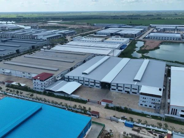
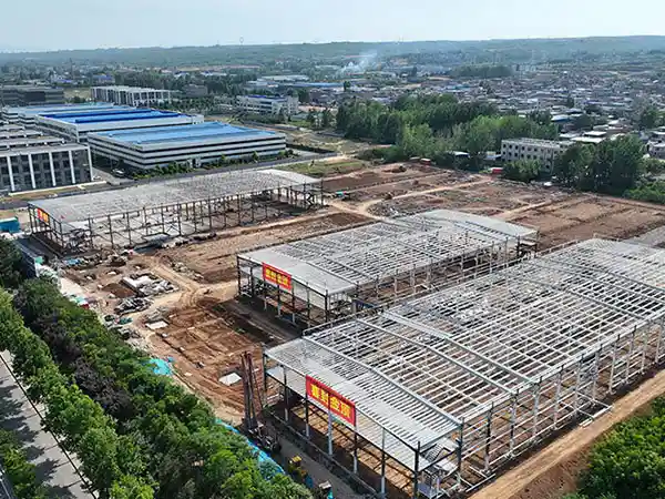
Industrial steel structure construction is a highly systematic process used to build facilities like factories, warehouses, power plants, processing facilities, and large-scale workshops. Unlike traditional construction, it relies heavily on prefabrication, where major components are manufactured off-site in a controlled factory environment and then transported to the site for assembly.

Industrial Steel Building Construction Process

Industrial steel structure construction

The construction process of an industrial steel structure is a complex and multi-stage endeavor that prioritizes precision, efficiency, and safety.

1. Design and Planning:

Conceptual Design & Feasibility: This initial stage involves understanding the client’s needs, project requirements, and site conditions. Architects and engineers collaborate to develop conceptual designs.

Detailed Design & Engineering: Based on the conceptual design, detailed blueprints, specifications, and structural calculations are created. This includes determining the appropriate steel grades and types, considering load-bearing requirements, environmental factors, and regulatory standards. Computer-Aided Design (CAD) software is extensively used for precise drawings.

Permits and Approvals: Obtaining all necessary permits and approvals from local authorities is a critical step before any physical work begins.

2. Procurement and Material Preparation:

Material Selection & Acquisition: High-quality steel materials (sheets, profiles, coils) are selected and ordered based on the detailed design.

Quality Inspection of Raw Materials: Incoming raw materials undergo strict inspections to verify they meet quality and strength standards, including checks for size, specifications, surface quality, and certification documents.

Material Cutting: Steel is cut to the desired sizes and shapes using various methods such as shearing, sawing, flame cutting, laser cutting, or plasma cutting, often employing CNC (Computer Numerical Control) machines for precision.

Bending and Shaping: Depending on the design, steel components like flanges and webs may be bent or pressed to achieve specific shapes and dimensions.

3. Fabrication (Off-site Manufacturing):

Sub-Assembly/Fitting: Individual steel components (beams, columns, trusses, etc.) are meticulously fitted together and temporarily connected, often using tack welding to hold them in place at the correct angles.

Welding and Joining: The primary method for joining steel components is welding (e.g., MIG, TIG, arc welding). Skilled welders ensure strong and durable connections. Bolting is also used, especially where disassembly or modification might be required. Reinforcing ribs and cleats are also welded.

Straightening: After welding, components may undergo straightening to remove any warping and ensure flatness and accurate edges.

For more detailed information about the construction process of industrial steel structure, please click to visit: https://www.meichensteel.com/a/news/industrial-steel-structure-construction-process.html

Industrial steel structures, while inherently non-combustible, are susceptible to significant strength loss and deformation when exposed to the high temperatures generated during a fire. This can lead to structural collapse, posing a severe risk to life and property. Therefore, fire resistance is a critical consideration in the design and construction of industrial steel structures.

Fire resistance of industrial steel structures

Industrial steel structures

1. How Fire Affects Steel Structures:

Loss of Strength and Stiffness: Steel’s yield strength and modulus of elasticity significantly decrease as temperature rises. While steel doesn’t melt until around 1300°C, it can lose about half its strength at 650°C, and structural integrity can be compromised as low as 400°C.
Thermal Expansion and Deformation: Steel expands when heated. If restrained, this expansion can induce stresses, leading to buckling, twisting, or warping of members.

Connection Damage: High temperatures can weaken or destroy bolts, welds, and other connections, further compromising the overall stability of the structure.
Microstructural Changes: Prolonged exposure to very high temperatures (above 700-800°C) followed by rapid cooling (e.g., from firefighting water) can lead to permanent changes in the steel’s microstructure, such as the formation of brittle martensite, even if visible deformation is minimal.

2. Fire Resistance Requirements:

Building codes and regulations specify the required fire resistance ratings for different building types and elements, often expressed in minutes (e.g., 30, 60, 90, 120, 180, 240 minutes). This rating indicates the time a structure must withstand a standard fire test without collapsing, allowing for occupant evacuation and firefighting efforts.

Factors influencing the required fire resistance include the building’s purpose, height, area, occupancy, and the type and quantity of combustible materials present.

More detailed information on the fire resistance of industrial steel structures can be found at: https://www.meichensteel.com/a/news/fire-resistance-of-industrial-steel-structures.html

Steel structure factories are widely used in industrial settings due to their durability, cost-effectiveness, and quick construction. However, like any other structure, they require regular maintenance to ensure long-term performance, safety, and structural integrity. Proper maintenance prevents corrosion, structural failures, and operational disruptions, ultimately saving costs on major repairs or replacements.

Steel Structure Factory Maintenance

Steel Structure Factory

Maintaining a steel structure factory is crucial for ensuring its longevity, safety, and operational efficiency.

Why is Steel Structure Factory Maintenance Important?

Prevents Corrosion & Rust – Exposure to moisture, chemicals, and industrial pollutants can degrade steel over time.

Ensures Structural Stability – Loose bolts, cracked welds, or foundation issues can compromise safety.

Extends Lifespan – Regular upkeep can prolong the factory’s service life by decades.

Maintains Aesthetic & Functional Value – A well-maintained factory enhances operational efficiency and company image.

Complies with Safety Regulations – Many industries require periodic structural inspections to meet legal standards.

Steel Structure Factory Maintenance Steps

Steel Structure Factory

1. Regular Inspections

Visual Inspections: Check for signs of corrosion, rust, dents, cracks, or deformation.

Roof & Wall Cladding: Look for leaks, loose panels, or damaged insulation.

Foundation: Ensure no cracks or settling that could affect stability.

2. Corrosion Protection & Painting

Clean Surfaces: Remove dirt, grease, and rust before repainting.

Anti-Corrosion Coatings: Apply primer and paint suitable for industrial environments.

Galvanized Components: If the steel is galvanized, check for white rust or coating damage.

Touch-Up Repairs: Address small rust spots immediately to prevent spread.

3. Bolted & Welded Connections

Tighten Loose Bolts: Vibration and load changes can loosen bolts over time.

Check Welds: Look for cracks or fatigue, especially in high-stress areas.

More details about how to maintain the steel structure plant can be clicked to visit:https://www.meichensteel.com/a/news/steel-structure-factory-maintenance.html

Shortening the construction cycle of steel structures is a critical goal for many projects, as it can significantly reduce costs and accelerate project handover. Here are some key tips and strategies to achieve this.

Tips for shortening the construction cycle of steel structures

steel structures

I. Pre-Construction & Planning Phase:

Early Contractor Involvement (ECI):

Engage fabricators and erectors early in the design phase. Their practical experience can identify potential fabrication and erection challenges, leading to design optimizations that save time and money later.

This allows for better coordination between design, fabrication, and construction, minimizing rework and delays.

Thorough Design and Detailing:

Detailed and Accurate Drawings: Invest in high-quality, precise structural steel detailing. Errors in drawings lead to costly rework, delays, and material waste on site.

BIM (Building Information Modeling): Utilize BIM software to create 3D models. This allows for clash detection (identifying conflicts between structural, architectural, and MEP elements) early on, reducing surprises during construction. It also streamlines communication among all stakeholders.

Standardization: Where possible, standardize connection details and component sizes. This simplifies fabrication and speeds up assembly.

Simplicity in Design: A simpler design with fewer complex connections or unique parts will naturally lead to faster fabrication and erection.

Comprehensive Planning & Scheduling:

Detailed Project Schedule: Create a realistic and detailed project schedule that accounts for all phases, including material procurement, fabrication, transportation, and erection.

Risk Assessment and Contingency Planning: Identify potential delays (e.g., weather, material shortages, labor availability, permitting issues) and develop contingency plans to mitigate their impact.

Optimized Resource Allocation: Ensure adequate availability of skilled labor, equipment (cranes, specialized tools), and materials. Avoid over-staffing in limited spaces, which can reduce efficiency.

Early Permitting: Start the permitting process as early as possible, as this can often be a significant source of delays.

Optimized Material Procurement and Supply Chain:

Reliable Suppliers: Partner with reputable steel suppliers and fabricators who have a proven track record of on-time delivery and quality.

Early Material Orders: Order steel and other critical components well in advance to avoid delays caused by material shortages or long lead times.

Just-in-Time Delivery (JIT): Coordinate material deliveries to align with the construction schedule, minimizing the need for large on-site storage areas and potential damage.

Local Sourcing: If feasible, source materials locally to reduce transportation times and costs.

II. Fabrication Phase:

steel structures

Prefabrication and Modular Construction:

Maximize Off-Site Fabrication: Fabricate as much of the steel structure as possible off-site in a controlled factory environment. This allows for higher precision, better quality control, and less reliance on weather conditions.

For more detailed information on tips to shorten the construction cycle of steel structures visit: https://www.meichensteel.com/a/news/tips-for-shortening-the-construction-cycle-of-steel-structures.html

A slewing bearing (or slew ring) is a large-diameter rotational rolling-element bearing designed to carry heavy, slow-turning, or slow-oscillating loads. It’s the critical component that allows massive machinery like cranes, excavators, and wind turbines to rotate smoothly and safely.

The load capacity is the single most important parameter when selecting a slewing bearing. It defines the maximum forces the bearing can withstand without failure. The double-row ball slewing ring is a specific design engineered to handle exceptionally high loads, particularly tilting moments.

Load Capacity of Double Row Ball Slewing Bearings

Double Row Ball Slewing Bearings

Combined Load Handling: Unlike simpler bearings, double-row ball slewing bearings are specifically designed to simultaneously handle a combination of:

Axial Loads: Forces acting along the axis of rotation (e.g., vertical weight from a crane boom).

Radial Loads: Forces acting perpendicular to the axis of rotation (e.g., side forces from a robotic arm).

Overturning Moments (Tilting Moments): Torques caused by eccentric loads that try to tip or rotate the bearing (e.g., twisting forces on a wind turbine blade). This is where they particularly shine.

Enhanced Capacity vs. Single-Row: The presence of two rows of rolling elements significantly increases their load-bearing capabilities compared to single-row slewing bearings of the same size. This is because the load is distributed over more contact points, reducing stress on individual components.

Optimized Raceways: Many double-row designs feature two independent raceways, often with different ball diameters. The upper and lower raceways are typically designed with 90° bearing angles, which allows them to effectively bear large axial forces and tilting moments.

Suitable for High Static and Dynamic Loads: While the rotational speed of slewing bearings is generally slow, their load capacity primarily refers to their static load capacity. Double-row ball bearings are built to withstand considerable static loads and also perform well under dynamic operating conditions.

Stiffness and Stability: The double-row configuration inherently provides greater stiffness and stability, minimizing deformation and deflection even under extreme loads.

Factors Influencing Load Capacity:

Double Row Ball Slewing Bearings

Bearing Dimensions: The outer diameter, inner diameter, and overall height of the bearing directly impact its load capacity. Larger bearings generally have higher capacities.

Ball Diameter: The size of the steel balls used plays a crucial role. Larger balls can carry more load.

Material Quality: High-strength steels and advanced manufacturing processes contribute to the overall durability and load resistance.

Raceway Design: The specific geometry and heat treatment of the raceways are critical for distributing stress and ensuring longevity.

Presence of Gearing: Bearings with integrated gear teeth (internal or external) will also have specifications related to the gear’s torque capacity.

More about the double row of ball slewing bearings bearing capacity how detailed information can be clicked to visit: https://www.mcslewingbearings.com/a/news/load-capacity-of-double-row-ball-slewing-bearings.html

Installing a double-row ball slewing bearing is a complex process that requires precision and adherence to manufacturer guidelines. Here’s a general outline of the steps involved, along with key considerations. Always refer to the specific installation manual provided by the bearing manufacturer for detailed instructions and torque specifications for your particular bearing model.

Double-row Ball Slewing Bearing Installation

Double-row Ball Slewing Bearing

I. Pre-Installation Checks and Preparation:

Inspect the Bearing:

Verify that the slewing bearing matches the specifications in your order.

Check for any damage incurred during transportation. Ensure seals are intact and there are no visible deformities.

Confirm that the lubrication holes on the bearing align with the host machine’s refueling method.

Prepare the Mounting Surfaces:

Cleanliness is paramount: Ensure both the host machine’s mounting platform and the slewing bearing’s mounting surfaces are absolutely clean and free from any debris, dirt, welding slag, burrs, paint, or other contaminants. Even small particles can significantly impact performance and lifespan.

Flatness and Rigidity: The mounting surfaces must be precisely machined, flat, and rigid enough to prevent deformation under load. Double-row ball slewing bearings are sensitive to unevenness, which can lead to localized stress and premature wear. Check for flatness deviations with a feeler gauge. If gaps exist, shims may be required to level the surface, but this should be done with extreme care and according to manufacturer recommendations.

Stress Relief: If the mounting bracket was welded, it should undergo internal stress relief heat treatment and then be machined to ensure flatness.

Soft Zone Placement:

Slewing bearings have an “unhardened” or “soft” zone in their raceway, typically marked with an “S” or a blocked hole. This soft zone should be positioned in the non-load area or non-constant load area of your application. For lifting machinery, it’s often recommended to place it at a 90° angle to the boom’s direction (the direction of maximum load). If both inner and outer rings have soft zones, they should be staggered, usually by 180°.

For more details on how to install double rows of ball slewing bearings click to visit: https://www.mcslewingbearings.com/a/news/double-row-ball-slewing-bearing-installation.html

Non-standard slewing bearings are crucial components in various heavy machinery and precision equipment, designed to handle significant axial, radial, and moment loads in highly specialized applications. Unlike standard bearings, their customization process is intricate, involving close collaboration between the client and the manufacturer to meet unique operational demands.

Non-standard slewing bearing customization process

slewing bearing

1. Initial Consultation and Requirement Gathering

The process begins with a comprehensive understanding of the client’s needs. This involves:

Application Analysis: Understanding the specific machine or system where the slewing bearing will be used. This includes factors like the type of equipment (cranes, excavators, wind turbines, medical equipment, robotics, etc.), its operating environment (marine, high/low temperature, dusty, corrosive), and overall performance requirements.

Load Analysis: Detailed information on the static and dynamic loads the bearing will endure, including axial, radial, and overturning moment loads, as well as shock loads and vibration.

Dimensional Constraints: Precise dimensions of the mounting space, including outer diameter, bore size, width, and any specific mounting hole configurations.

Performance Specifications: Required rotational speed, precision (runout tolerances), stiffness, torque requirements, and expected service life.

Environmental Factors: Exposure to moisture, saltwater, chemicals, dust, extreme temperatures, and the need for specialized sealing or corrosion protection.

Special Features: Any unique requirements such as integrated gearing (internal, external, helical, worm gears), lubrication systems, control devices, or monitoring systems.

Material Preferences: While manufacturers often recommend materials, clients may have specific preferences or requirements for certain alloys (e.g., high-strength steel, stainless steel, specialized alloys like 42CrMo4, 50Mn, or even aluminum for lightweight applications).

Compliance and Certifications: Any industry-specific standards (e.g., ISO, AGMA, DEF STAN) or certifications required for the bearing.

2. Design and Engineering

Once the requirements are thoroughly understood, the engineering team commences the design phase:

Conceptual Design: Engineers develop initial concepts based on the gathered data, considering different slewing bearing types (e.g., four-point contact ball bearings, crossed cylindrical roller bearings, triple-row roller bearings, combined roller/ball bearings) that best suit the application.

Detailed CAD Modeling: Using advanced 3D modeling software, a detailed design of the non-standard bearing is created. This includes precise geometries of the inner and outer rings, raceways, rolling elements, cages/spacers, gearing, and sealing systems.

Material Selection: Based on load, environment, and performance requirements, appropriate materials are selected for the rings, rolling elements, and other components. This often involves specialized heat treatments to achieve desired hardness, wear resistance, and fatigue strength.

Structural Analysis (FEA): Finite Element Analysis (FEA) simulations are performed to validate the design’s integrity under various load conditions, predict stress distribution, deflection, and stiffness, and optimize the design for maximum performance and lifespan.

Lubrication System Design: Designing or recommending a suitable lubrication system (grease or oil) and specifying lubricants based on operating conditions. This includes determining lubrication intervals and potential for advanced lubrication systems.

More detailed information about the process of customizing non-standard slewing bearings can be found by clicking Visit:https://www.mcslewingbearings.com/a/news/slewing-bearing-customization-process.html

Slewing bearings withstand radial loads through a combination of their internal geometry, the distribution of force across multiple rolling elements, and the structural rigidity of their rings.

How Slewing Bearings Withstand Radial Loads

Slewing bearings

1. The Foundation: What is a Radial Load?

First, let’s be clear on the force we’re talking about. In the context of a slewing bearing (like the one on a crane), a radial load is a force that pushes or pulls on the bearing from the side, perpendicular to the central axis of rotation.

Example: The force of the wind pushing against the side of a long crane boom.

Contrast with other loads:

Axial (or Thrust) Load: A force acting parallel to the axis of rotation (e.g., the weight of the crane’s cabin and boom pushing straight down).

Moment (or Tilting) Load: A force that tries to tip or overturn the bearing (e.g., the weight of a heavy object lifted at the end of the crane boom).

Slewing bearings are remarkable because they are designed to handle all three types of loads simultaneously. Their ability to handle radial loads is a direct result of this multi-load design.

2. The Core Mechanism: Raceway Geometry and Contact Angle

The “magic” happens inside the bearing, specifically in the way the rolling elements (balls or rollers) make contact with the inner and outer rings (the raceways).

A. For Four-Point Contact Ball Bearings (The Most Common Type)

This is the classic design. Imagine cutting a slewing bearing in half. You would see that the groove (raceway) the balls run in is not a simple semi-circle. It’s shaped like a gothic arch or two shallow V’s.

How it Works: When a radial load pushes the inner ring sideways, the balls are forced up the angled raceways of both the inner and outer rings.

The Contact Angle: The force is transmitted through the balls at an angle (the “contact angle”). This angle means that a single radial force is resolved into two components: one that is axial and one that is radial.

The Key Takeaway: Because the ball contacts the raceway on an angle, it can resist forces from both the side (radial) and top/bottom (axial) simultaneously. A single ball acts like two separate bearings pushed against each other at an angle, all in one compact design.

B. For Crossed Roller Bearings

This design is even more explicit in how it handles loads from different directions.

How it Works: Cylindrical rollers are arranged in a crisscross pattern, with each roller oriented at 90 degrees to the one next to it.

For more detailed information on how slewing bearings can withstand radial loads, click to visit:https://www.mcslewingbearings.com/a/news/how-slewing-bearings-withstand-radial-loads.html