
Selecting a crossed roller bearing for a CNC rotary table is rarely a simple catalogue lookup. The bearing sits at the intersection of positioning accuracy, structural rigidity, and long-term reliability, so a wrong choice shows up months later as chatter marks, thermal drift, or a table that no longer holds tolerance. Engineers searching for guidance on this topic usually have a specific machine design in front of them and need to justify a decision to a project manager, a customer, or themselves. This article walks through the technical criteria that actually determine performance, the trade-offs between common bearing configurations, and the supplier checks that separate a reliable precision bearing from an expensive spare part.
What a Crossed Roller Bearing Really Does in a Rotary Table
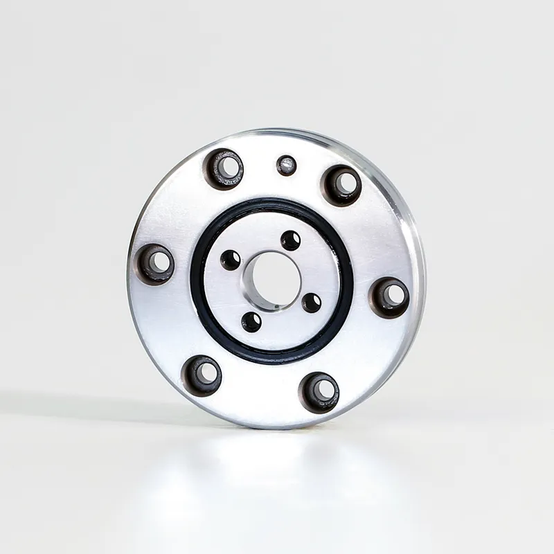
A crossed roller bearing uses cylindrical rollers arranged at 90 degrees to one another in a single raceway, alternating in orientation. That arrangement lets one compact bearing absorb radial load, axial load, and tilting moment simultaneously. In a rotary table, this single-bearing capability is the main appeal: it replaces a multi-bearing stack, shortens the axial height of the assembly, and removes the tolerance stack-up that comes with pairing a thrust bearing and a radial bearing.
Load path and rigidity
Rigidity matters more than raw load rating in most machining applications. A table that deflects under cutting force will produce dimensional error even if the servo loop is perfectly tuned. Crossed roller bearings offer high stiffness because the rollers contact the raceway over a line rather than a point, and because preload removes internal clearance. The practical consequences are reduced tool deflection, better surface finish, and higher achievable feed rates.
Why the arrangement affects indexing accuracy
In an indexing table, the bearing defines the axis of rotation. Any runout in the inner or outer ring is translated directly into angular positioning error at the workpiece. This is why precision grades and matched ring pairs are specified for rotary axes rather than for general machinery.
Core Selection Parameters
Load capacity and moment load
Start by calculating the combined load case: workpiece weight, fixture weight, cutting forces in three axes, and the moment arm created by an off-centre workpiece. Moment load is frequently underestimated. A heavy part mounted at the edge of a table creates a tilting moment that can exceed the axial load by a large factor. The bearing must be rated for the resulting equivalent load, not just the vertical weight.
Accuracy grade and runout
Precision classes such as P5, P4, and P2 describe permissible radial and axial runout. Higher grades cost more and take longer to deliver. For a grinding or measuring application, P4 or better is normally justified. For a general-purpose positioning table, P5 may be entirely adequate. Over-specifying accuracy is one of the most common ways to inflate machine cost without improving output.
Preload and friction torque
Preload eliminates clearance and increases stiffness, but it also increases friction torque and heat generation. In a worm-gear table, excessive preload can distort the gear mesh and accelerate wear. In a direct-drive table, friction torque directly affects motor sizing and current draw. The right preload is a balance point determined by required stiffness and available drive torque, not simply the highest value available.
…
For more detailed information on how to select crossed roller bearings for CNC rotary tables, please click here: https://www.bobibearing.com/a/bearing-knowledge/crossed-roller-bearings-for-cnc-rotary-tables-choose.html