A crane is only as reliable as its slewing bearing. This critical component enables 360-degree rotation while supporting immense axial, radial, and tilting loads. Neglecting its maintenance can lead to catastrophic failures, costly downtime, and significantly shortened equipment life. However, with a structured maintenance regime, operators can dramatically extend crane lifespan and reduce total cost of ownership. This article outlines the essential practices for slewing bearing care, drawing on industry best practices and the specialized expertise of LYMC in heavy-duty rotating solutions.
The Critical Role of the Slewing Bearing in Crane Longevity
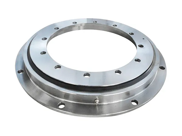
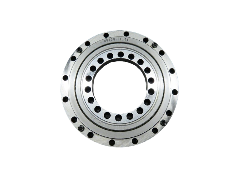
The slewing bearing acts as the mechanical pivot point between the crane’s upper structure and its undercarriage or foundation. It must withstand extreme forces while maintaining smooth, precise rotation. Over time, wear accumulates from friction, contamination, and micro-movements. Even minor degradation in the bearing’s raceways or rolling elements can amplify vibrations, increase drive motor loads, and accelerate fatigue in surrounding structures. Proper slewing bearing maintenance is therefore not optional—it is a direct determinant of the crane’s service life. Operators who treat the bearing as a consumable item without proactive care often face premature replacement costs that dwarf the investment in regular upkeep.
Common Causes of Slewing Bearing Failure
Understanding failure modes helps prioritize maintenance actions. The most frequent culprits include:
- Inadequate lubrication: Insufficient grease or wrong type leads to metal-to-metal contact and rapid wear.
- Contamination: Dirt, water, and abrasive particles enter through damaged seals, causing three-body abrasion.
- Uneven loading: Repeated off-center loads or exceeding rated capacity induces local overstress and brinelling.
- Corrosion: Moisture trapped in the bearing raceway initiates pitting and flaking.
- Bolt loosening: Loss of preload in mounting bolts allows relative motion, fretting, and structural misalignment.
Each of these issues can be mitigated through systematic inspection and corrective action before irreversible damage occurs.
…
For more information on proper slewing bearing maintenance to maximize crane lifespan, please click here:https://www.mcslewingbearings.com/a/news/bearing-maintenance-.html