Vibrating screens are essential equipment in many industries for separating materials by particle size. Both linear and rotary vibrating screens achieve this, but they differ significantly in their mechanism, application, and performance.
Differences Between Linear Vibrating Screen and Rotary Vibrating Screen
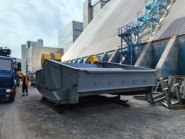
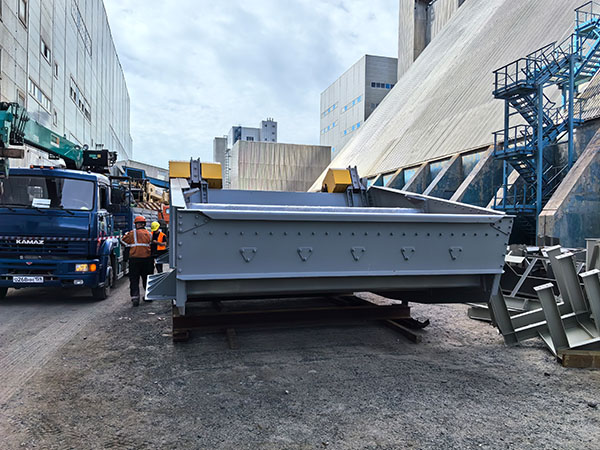
Linear Vibrating Screen
A linear vibrating screen moves material in a straight line.
Here’s how it generally works and its characteristics:
Movement: The screen box vibrates in a linear, back-and-forth motion, which propels the material along the screen surface. This motion is typically generated by two unbalanced motors rotating in opposite directions.
Angle: The screen surface is usually inclined at a slight angle to aid material flow.
Separation Principle: The linear motion helps stratify the material, with finer particles falling through the mesh openings while coarser particles move along the screen.
Advantages:
High screening efficiency for a wide range of materials.
Suitable for both wet and dry screening.
Can handle larger capacities for certain applications.
Less prone to blinding (clogging of screen mesh) with certain materials due to the strong linear action.
Applications: Commonly used in mining, aggregates, chemical, food, and fertilizer industries for sizing, scalping, and dewatering.
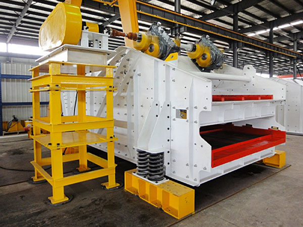
Rotary Vibrating Screen (Circular Vibrating Screen)
A rotary vibrating screen, also known as a circular vibrating screen or gyratory screen, uses a circular or elliptical motion to separate materials.
Here’s a breakdown of its characteristics:
Movement: The screen box performs a circular, elliptical, or parabolic motion. This is typically achieved by a single unbalanced motor mounted centrally on the screen. The motion creates a continuous rolling and stratifying action of the material.
…
For more detailed information about the difference between linear vibrating screen and rotary vibrating screen, please click here: https://www.hsd-industry.com/news/differences-between-linear-vibrating-screen-and-rotary-vibrating-screen/