Graphite soft felt is a flexible, high-temperature insulation material made from carbon or graphite fibers. Its performance is characterized by a unique combination of thermal, chemical, mechanical, and electrical properties.

Graphite Soft Felt Performance

Graphite soft felt

1. Thermal Performance:

High-Temperature Stability: This is its primary advantage. It can withstand extremely high temperatures, typically up to 2500°C (4532°F) and even higher (up to 3000°C) for short durations in inert or vacuum atmospheres. In oxidizing atmospheres, its use is limited to around 400-500°C.

Low Thermal Conductivity: It’s an excellent thermal insulator, especially in vacuum or inert gas environments. Thermal conductivity typically ranges from 0.08 to 0.2 W/m·K at room temperature, and it generally decreases with increasing temperature up to a certain point (around 1500-2000°C) before radiation effects start to dominate and increase apparent conductivity.

Low Specific Heat: It heats up and cools down relatively quickly, which can be advantageous for rapid thermal cycling.

Good Thermal Shock Resistance: Due to its fibrous nature and low coefficient of thermal expansion, it can withstand rapid temperature changes without cracking or degrading.

Low Outgassing (after proper treatment): When properly purified and baked out, it exhibits low outgassing, making it suitable for high-vacuum applications.

2. Chemical Performance:

High Purity: Typically has a high carbon content (often >99%, with some grades >99.9%) and low ash content. This minimizes contamination in high-temperature processes.

Chemical Inertness: Highly resistant to most corrosive chemicals, acids, bases, solvents, and molten metals (except strong oxidizing agents or metals that form carbides at very high temperatures).

Non-Wetting: Generally not wetted by many molten metals, which can be beneficial in metallurgical applications.

3. Mechanical Performance:

Flexibility and Conformability: Being “soft,” it can be easily bent, wrapped around complex shapes, or compressed to fit into tight spaces.

Low Density: Typically very lightweight (e.g., 0.08 – 0.2 g/cm³), which reduces the overall weight of insulation systems.

Low Strength: It has low tensile and compressive strength. It’s not a structural material and can be easily torn or damaged if handled improperly.

More detailed information about the performance of graphite felt can be found by clicking on the following link: https://www.czgraphite.com/a/news/graphite-soft-felt-performance.html

Graphite plays critical role in heat treatment processes due to its exceptional thermal stability, chemical inertness, and excellent heat conductivity. Widely used in high-temperature furnaces, graphite components—such as insulation boards, heating elements, and crucibles—help maintain consistent temperature control and ensure clean processing environment.

Graphite in Heat Treatment Role

Graphite

Furnace Components & Fixtures:

High-Temperature Stability: Graphite can withstand very high temperatures (sublimes at ~3650°C) without melting, making it ideal for furnace linings, insulation, trays, boats, grids, and fixtures used to hold parts during heat treatment.

Low Thermal Expansion: It has a low coefficient of thermal expansion, meaning it doesn’t change size or shape significantly with temperature changes, preventing distortion of the fixtures or the parts they hold.

Thermal Shock Resistance: Graphite can withstand rapid temperature changes without cracking, which is common in heat treatment cycles.

Machinability: It can be easily machined into complex shapes for custom fixtures.

Heating Elements:

Electrical Conductivity: Graphite is a good electrical conductor, allowing it to be used as a resistance heating element in vacuum furnaces or furnaces with controlled atmospheres. It heats up when an electric current passes through it.

High Emissivity: It radiates heat efficiently, contributing to uniform heating within the furnace.

Susceptors (for Induction Heating):

In induction heating, a non-conductive material might need to be heated. A graphite susceptor can be placed near or around the material. The induction coil heats the graphite susceptor, which then radiates heat to the target material.

Crucibles and Molds:

Chemical Inertness: Graphite is relatively inert and does not react with many molten metals or materials being heat-treated, preventing contamination.

Non-Wetting: Many molten metals do not “wet” graphite, making it easier to remove the treated part or molten material from graphite crucibles or molds.

Thermal Conductivity: Good thermal conductivity allows for even heating and cooling of the contents within a graphite crucible.

Graphite

Protective Atmospheres & Carburizing Agents:

Oxygen Scavenger: In some applications, particularly at very high temperatures in a slightly oxidizing environment, graphite can act as an oxygen scavenger by

reacting with oxygen to form CO or CO2, thus protecting the workpiece from oxidation.

For more detailed information about the role of graphite in heat treatment, click to visit: https://www.czgraphite.com/a/news/graphite-in-heat-treatment-role.html

Choosing the right graphite ring for high-temperature applications requires careful consideration of several factors to ensure optimal performance and longevity. Here’s a guide to help you make the best selection.

Graphite Ring Choose

graphite ring

1. Understand the Operating Conditions:

Temperature: Determine the continuous and maximum operating temperatures. Graphite rings can withstand very high temperatures, but their performance can be affected by the presence of oxygen.

Oxidizing Environments (e.g., air): The maximum temperature is typically around 450-500°C (842-932°F). Some sources mention up to 650°C (1202°F), but oxidation becomes more significant at these higher temperatures

Steam Environments: Graphite can handle temperatures up to 650°C (1202°F).

Non-Oxidizing Environments (e.g., vacuum, inert gases): Graphite can withstand exceptionally high temperatures, potentially reaching up to 3000°C (5432°F).

Pressure: Identify the system’s operating pressure. Higher density graphite rings offer greater pressure resistance and can handle pressures exceeding 300 bar (around 4350 psi).

Media: Determine the chemical compatibility requirements. Graphite generally offers excellent resistance to a wide range of media, including hot water, steam, hydrocarbons, chemicals, and solvents, across a broad pH range (0-14). However, it’s not suitable for strong oxidizing agents.

Speed (for dynamic applications): If the ring will be used in rotating equipment, consider the shaft speed. Different graphite grades and ring densities may be recommended for various speed ranges.

Static or Dynamic Application: Rings for static applications (e.g., gaskets in heat exchangers, flanges) and dynamic applications (e.g., sealing in pumps, valves, compressors) might have different design considerations.

2. Consider the Material Properties of Graphite:

Purity: Higher purity graphite (higher carbon content, typically >98%) generally offers better sealing efficiency, corrosion resistance, and oxidation resistance. Nuclear-grade graphite with even higher purity is available for critical applications.

Density: Density affects the ring’s strength, pressure resistance, and sealing capability. Higher density rings (e.g., 1.8 g/cm³) are suitable for higher pressures. Common density ranges are 1.3 to 1.8 g/cm³.

Ash Content: Lower ash content indicates higher purity and can be important for certain sensitive applications.

Sulphur, Chloride, and Fluoride Content: Low levels of these impurities are crucial to minimize corrosion, especially in steam and water environments. Good quality graphite should have sulphur content below 300-500 ppm, and chlorides and fluorides below 50 ppm (industrial grade) or even 20 ppm (nuclear grade).

More detailed information on how to select the right graphite ring for high temperature applications can be found at: https://www.czgraphite.com/a/news/graphite-ring-choose.html

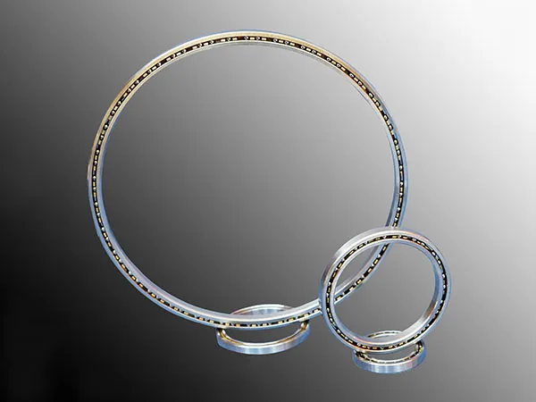
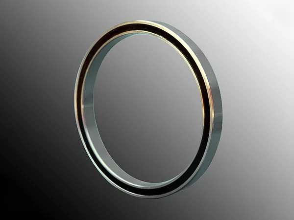
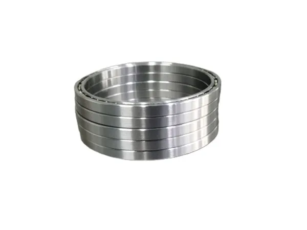
Installing thin section bearings requires precision and careful handling due to their delicate nature. Unlike standard bearings, their thin design makes them more susceptible to distortion if not handled correctly.

How to install thin section bearings

thin section bearings

1. Preparation is Key

Cleanliness: Ensure the shaft, housing, and bearing are meticulously clean and free of any dust, dirt, or foreign particles. Contaminants are a major cause of bearing failure.

Inspection:

Bearing: Visually inspect the bearing for any damage, such as nicks, burrs, or corrosion. Thin section bearings can be challenging to measure accurately with traditional tools (calipers, micrometers) in their free state as they aren’t perfectly round. Specialized tools like CMMs (Coordinate Measuring Machines) or air gages are often needed for accurate measurement.

Mating Components: Critically examine the shaft and housing for roundness and flatness. Thin section bearings conform to their mating components, so any imperfections will affect their performance and lifespan. Manufacturers typically provide strict tolerances (e.g., h7 for shafts and H7 for housings).

Lubrication: Thin section bearings usually come with a preservative oil. This should be cleaned off, and the bearing should be lubricated with a suitable oil or grease for your specific application before installation. Sealed bearings are pre-filled with grease.

Tools: Gather the necessary tools. This may include:

Arbor press or hydraulic press (recommended for most installations)

Mounting tools/fixtures (designed to apply even pressure to the correct ring)

Heating equipment (induction heater, oil bath) for shrink fitting

Cooling agents (dry ice) for expansion fitting

Feeler gauges (for checking internal clearance after installation)

Torque wrench (for clamping fasteners)

Clean cloths/wipes

2. Installation Methods

thin section bearings

The method chosen depends on the fit (interference or clearance) and the bearing type.

More detailed information about how to install thin section bearings can be found by clicking visit: https://www.lynicebearings.com/a/blog/how-to-install-thin-section-bearings.html

Reducing noise in thin section bearings involves addressing potential sources at various stages: bearing selection, installation, lubrication, and operation. Thin section bearings are particularly sensitive due to their high diameter-to-cross-section ratio, making them more flexible and susceptible to distortion.

How to reduce the noise of thin section bearings

thin section bearings

Bearing Selection & Design:

Higher Precision Grade: Choose bearings with higher ABEC (Annular Bearing Engineers’ Committee) or ISO (International Organization for Standardization) precision classes. Higher precision means tighter tolerances on raceway geometry, ball sphericity, and surface finish, leading to smoother operation.

Internal Clearance: Select the appropriate internal clearance (C2, C0, C3, etc.). Too much clearance can lead to ball skidding and noise, while too little (or excessive preload) can increase friction, heat, and noise. The correct clearance depends on the application, fit, and operating temperature.

Cage (Retainer) Material & Design:

Polymer Cages: Nylon (polyamide) or PEEK cages can dampen vibrations and run quieter than steel cages, especially at high speeds.

Crown-type or Snap-over Cages: These can sometimes be quieter than ribbon-type cages.

Full Complement (No Cage): While offering higher load capacity, these are generally noisier due to ball-to-ball contact.

Ball Material: Ceramic balls (e.g., Silicon Nitride, Si3N4) are lighter, harder, and smoother than steel balls. This reduces centrifugal forces, wear, friction, and can lead to quieter operation.

Seals and Shields: While primarily for keeping contaminants out and lubricant in, they can offer a slight damping effect. However, rubbing seals can also be a source of noise if not properly designed or lubricated.

Proper Installation & Mounting (CRITICAL for Thin Sections):

thin section bearings

Housing and Shaft Geometry:

Roundness & Cylindricity: Thin section bearings conform to the shape of the shaft and housing. Any out-of-roundness or taper in the mating components will distort the bearing rings, leading to uneven load distribution, increased stress, and noise. Use high-precision machining for mating surfaces.

Concentricity & Perpendicularity: Ensure shaft and housing bores are concentric and shoulders are perpendicular to the axis. Misalignment is a major noise contributor.

More detailed information about how to reduce the noise of thin section bearings can be found by clicking visit: https://www.lynicebearings.com/a/blog/how-to-reduce-the-noise-of-thin-section-bearings.html

Choosing thin section bearings requires careful consideration of your application’s specific needs. These bearings are prized for their space-saving and weight-reducing characteristics, but their “thinness” also makes them more sensitive to certain factors.

How to Choose Thin Section Bearings

Understand Your Application’s Requirements:

This is the most crucial step. Define:

Loads:

Radial Load: Perpendicular to the shaft axis.

Axial (Thrust) Load: Parallel to the shaft axis.

Moment Load: A load that tends to cause rotation about an axis (tilting). Thin section bearings can handle moment loads, but the type and configuration are critical.

Magnitude and Direction: Quantify these loads. Are they static or dynamic?

Speed (RPM): Operating speed and any peak speeds. This affects lubrication and heat generation.

Space Envelope: What are the maximum allowable outer diameter (OD), inner diameter (ID), and width? This is often the primary driver for choosing thin section bearings.

Accuracy & Rigidity:

Runout: How much deviation from perfect rotation is acceptable?

Stiffness/Rigidity: How much will the bearing deflect under load? This is critical for precision applications.

Operating Environment:

Temperature: Operating range, extremes.

Contamination: Presence of dust, dirt, moisture, chemicals. This dictates sealing requirements.

Corrosion: Will the bearing be exposed to corrosive substances?

Life Expectancy: How many hours or revolutions does the bearing need to last? (L10 life)

Maintenance Requirements: Is relubrication possible or desired?

Select the Bearing Type (Based on Load):

Thin section bearings come in three main contact types:

Type C (Radial Contact / Conrad):

Best for: Primarily radial loads. Can handle light to moderate thrust loads in one direction.

Characteristics: Deep groove, suitable for higher speeds.

Type A (Angular Contact):

Best for: Combined radial and thrust loads (thrust in one direction). Often used in pairs (duplexed) to handle thrust in both directions and increase moment capacity/stiffness.

Characteristics: Has a specific contact angle. Higher contact angles provide greater axial load capacity but lower radial capacity and speed capability.

More details about how to choose thin section bearings can be found by clicking visit: https://www.lynicebearings.com/a/blog/how-to-choose-thin-section-bearings.html

Thin-wall bearings are crucial components in industrial robots, enabling precision movement within a compact design. However, their thin cross-section makes them more susceptible to damage if not properly maintained. Extending their lifespan requires a proactive and consistent approach.

Thin-Wall Bearing Maintenance

Thin-Wall Bearing

1. Proper Lubrication: The Lifeline of Thin-Wall Bearings

Select the Right Lubricant: Choose a lubricant specifically recommended by the bearing or robot manufacturer. Consider factors like operating temperature, speed, load, and environmental conditions. Options include:

Grease: Suitable for most robot applications, offering good sealing and longevity. Ensure compatibility with seals (if present). Thin-section bearings are often shipped with a 20-30% fill of MIL-G-81322 grease for sealed types.

Oil: Can support higher speeds and offer better cooling but requires a more complex lubrication system. The oil level should typically reach the midpoint of the lowest rolling element in vertical mounts.

Solid Lubricants: For difficult-to-access bearings, consider porous polymers that release oil over time or dry film lubricants like Tungsten Disulphide or PTFE coatings.

Apply the Correct Amount: Avoid over-lubrication, which can attract contaminants, and under-lubrication, which leads to metal-on-metal contact and wear.

Lubrication Intervals: Follow the manufacturer’s recommended relubrication schedule. Adjust based on the severity of the operating conditions.

Maintain Cleanliness: Ensure the lubricant is free from contaminants. Clean the lubrication points before applying new lubricant.

2. Prevent Contamination: Shielding Against Damage

Seals and Shields: Utilize appropriate seals or shields to prevent the ingress of dust, dirt, moisture, and other debris. Inspect seals regularly for damage and replace them when necessary.

Clean Operating Environment: Minimize contaminants in the robot’s working environment.

Proper Storage: Store spare bearings in a clean, dry environment, ideally in their original packaging, to prevent corrosion and contamination.

3. Careful Handling and Installation: Setting the Stage for Longevity

Gentle Handling: Avoid dropping or subjecting bearings to impact loads during handling and installation.

Correct Tools and Techniques: Use the proper tools for mounting and dismounting bearings. Incorrect installation can lead to misalignment and premature failure.

Proper Alignment: Ensure accurate alignment of the bearing and connected components to prevent uneven load distribution and stress. Avoid excessive force during installation.

Thin-Wall Bearing

4. Regular Inspection and Monitoring: Early Detection is Key

Visual Inspections: Conduct routine visual checks for signs of wear, corrosion, damage, or leaks.

More detailed information about thin section bearing maintenance can be found by clicking visit: https://www.lynicebearings.com/a/blog/thin-wall-bearing-maintenance.html

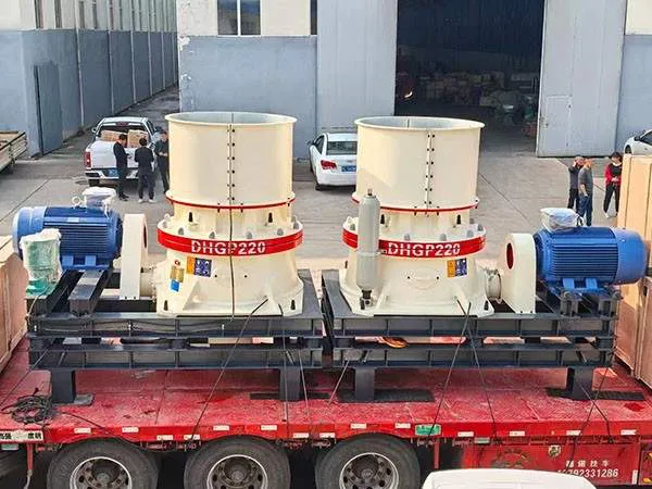
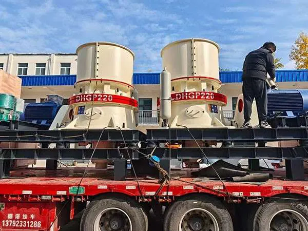
Cone crusher liner wear is a significant operational cost in the mining and aggregates industries. It’s influenced by a complex interplay of factors related to the material being crushed, the crusher’s operation, and the properties of the liners themselves.

Cone Crusher Liner Wear Reasons

Cone Crusher

1. Abrasive Properties of the Material (Rock/Ore):

Hardness and Abrasiveness: The harder and more abrasive the rock, the faster the liners will wear. Materials with high quartz content are particularly abrasive.

Particle Shape: Highly angular particles tend to cause higher wear due to increased friction and gouging.

Size Distribution of Feed:

Too small feed for the cavity: This can lead to excessive wear at the bottom of the liners as material grinds against them.

Too large or too coarse feed: This speeds up wear at the top of the liners and can cause abnormal wear patterns.

Poorly graded or segregated feed: Uneven distribution of material (e.g., large material on one side, small on the other) causes uneven wear, leading to premature replacement of liners even if parts are still good. Fines in the feed can also act like sandblasting, accelerating wear.

Moisture Content: High moisture content can affect the crushing process and potentially influence wear, sometimes causing clogging or slippage.

2. Crushing Mechanism and Forces:

Abrasion: This is the primary wear mechanism in cone crushers. As rock material is squeezed and compressed between the mantle and concave, there’s significant relative sliding and grinding action, which scrapes away material from the liner surfaces.

Impact: While cone crushers are primarily compression crushers, impact forces are still present, especially with larger feed material. The repeated impact of rocks against the liners contributes to wear.

Compression Pressure: The pressure exerted on the liners during crushing is a key factor in wear. Higher compression ratios and finer particle size distributions generally lead to higher pressures and more serious liner wear.

Fretting Corrosion: This occurs at the contact surfaces between the liners and the cone support, especially with small relative displacements. It involves mechanical-corrosive wear, leading to rubbing, adhesions, and cavities filled with wear products.

More detailed information about the causes of cone crusher liner wear can be found by clicking visit: https://www.yd-crusher.com/a/news/cone-crusher-liner-wear-reasons.html

Adjusting the speed of a cone crusher, specifically the eccentric speed (the speed at which the mainshaft gyrates), is a critical operational parameter that impacts throughput, product gradation, power draw, and wear.

How to adjust the speed of cone crusher

cone crusher

Primary Methods of Speed Adjustment:

Variable Frequency Drive (VFD) / Variable Speed Drive (VSD):

How it works: A VFD controls the electrical frequency supplied to the crusher’s electric motor. By changing the frequency, the motor’s RPM changes, which in turn changes the speed of the crusher’s drive pulley and thus the eccentric speed.

Advantages:

Offers precise and continuous speed adjustment.

Can be adjusted while the crusher is running (though often done incrementally).

Allows for soft starting, reducing mechanical stress.

Can be integrated into plant automation systems.

Implementation: This is the most common and flexible method in modern plants. It requires installing a VFD unit appropriately sized for the crusher motor.

Changing Pulleys/Sheaves:

How it works: The crusher is driven by a motor via a belt and pulley system. The speed ratio is determined by the diameter of the motor pulley (drive sheave) and the crusher pulley (driven sheave).

Crusher Speed = Motor Speed × (Diameter of Motor Pulley / Diameter of Crusher Pulley)

To change the crusher speed, you would replace either the motor pulley or the crusher pulley (or both) with ones of different diameters.

To increase crusher speed: Use a larger motor pulley or a smaller crusher pulley.

To decrease crusher speed: Use a smaller motor pulley or a larger crusher pulley.

Disadvantages:

Requires downtime to change pulleys.

Offers stepped, not continuous, adjustment.

Belt tension needs to be readjusted.

More labor-intensive.

Implementation: This is an older method or used for significant, less frequent speed changes.

Factors to Consider When Adjusting Speed:

cone crusher

Product Gradation:

Higher Speed: Generally produces a finer product and more cubical particles. It increases the number of crushing actions per unit of time.

More detailed information about how to adjust the speed of cone crusher can be clicked to visit: https://www.yd-crusher.com/a/news/how-to-adjust-the-speed-of-cone-crusher.html

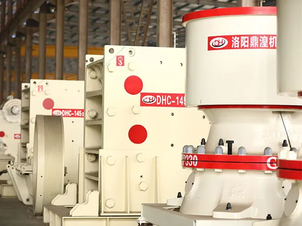
While both jaw crushers and cone crushers are essential in aggregate and mining operations, they are typically used at different stages and have distinct advantages. Cone crushers generally offer advantages over jaw crushers when used in secondary, tertiary, or quaternary crushing stages, after a primary jaw crusher has already done the initial size reduction.

Key Advantages of Cone Crushers Over Jaw Crushers

Cone Crushers

Superior Product Shape (Cubicity):

Cone Crusher: Produces a more cubical (equi-dimensional) product. This is due to the combination of compression and attrition as material is crushed between the mantle and bowl liner, and also due to inter-particle crushing when choke-fed. Cubical aggregate is preferred for concrete and asphalt as it provides better strength and workability.

Jaw Crusher: Tends to produce more elongated or flaky particles, especially with laminated or slabby feed rock.

Finer and More Consistent Product Size:

Cone Crusher: Can achieve a finer product size and a tighter particle size distribution. They are designed for producing precisely graded materials.

Jaw Crusher: Primarily designed for coarse primary crushing, so its product is larger and less uniform.

Higher Throughput (in Secondary/Tertiary Stages):

Cone Crusher: For a given physical size (in secondary/tertiary applications), a cone crusher often has a higher throughput capacity than a jaw crusher would if it were forced to produce a similarly sized product. The continuous crushing action contributes to this.

Jaw Crusher: Operates with an intermittent crushing action (once per revolution).

Cone Crushers

Higher Reduction Ratio (in its operating range):

Cone Crusher: Can achieve higher reduction ratios (e.g., 6:1 to 10:1 or even higher in some modern designs) efficiently when processing pre-crushed material.

Jaw Crusher: Typically offers reduction ratios of 3:1 to 5:1 for primary crushing.

More detailed information about the advantages of cone crusher compared with jaw crusher can be clicked to visit: https://www.yd-crusher.com/a/news/advantages-of-cone-crusher-over-jaw-crusher.html