Every vibrating screen operator knows that consistent screening performance depends on more than just starting the machine and feeding material. Quality Assurance (QA) and Quality Control (QC) tests form the backbone of reliable operation, helping to detect wear, misalignment, and process deviations before they lead to costly downtime or product quality failures. Whether you are new to screening operations or a seasoned professional, mastering these fundamental tests ensures your equipment delivers the expected gradation, throughput, and longevity. In this guide, we outline the core QA and QC tests that every operator should integrate into their routine, drawing on industry best practices and the engineering expertise of Haiside.
1. Pre-Operational Inspection: The Foundation of QA
Before any load is applied, a thorough pre-operational check verifies that the vibrating screen is mechanically sound and safe to start. This QA step establishes a baseline for all subsequent tests.
1.1 Visual and Structural Examination
Inspect the screen deck, side plates, cross beams, and support structure for cracks, deformation, or loose bolts. Particular attention should be paid to weld joints and areas around the exciter mounting. Haiside recommends using a calibrated torque wrench to verify that all fasteners meet the manufacturer’s specified torque values.
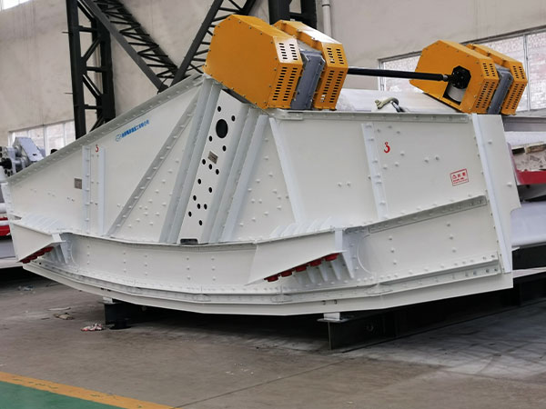
1.2 Vibration Mechanism Check
Ensure the exciter (vibrator) is correctly assembled with the proper oil level and no leaks. Rotate the exciter manually (if possible) to confirm free rotation without binding. Check that the drive belts or coupling are aligned and tensioned per specifications.
1.3 Safety Systems Verification
Test emergency stops, interlocks, and guards. Confirm that the screen is isolated from upstream and downstream equipment before start-up.
2. Dynamic Performance Tests: Amplitude, Frequency, and Stroke
Once the screen is running at no-load, operators must measure key vibration parameters to confirm the machine is operating within design tolerances.
2.1 Amplitude Measurement
Amplitude (travel) is the total displacement of the screen deck. Use a vibration analyzer or a simple amplitude measurement card to record the peak-to-peak displacement at all four corners of the deck. The acceptable variation between corners should be less than 10%. Haiside engineers emphasize that amplitude below specification reduces stratification efficiency, while excessive amplitude accelerates structural fatigue.
2.2 Operating Frequency (RPM)
Using a tachometer or built-in encoder, verify that the exciter speed matches the manufacturer’s target frequency. Any deviation of more than 5% may indicate belt slippage, electrical frequency issues, or incorrect pulley ratios.
…
For more detailed information on quality assurance and quality control testing that vibrating screen operators should know, please click to visit: https://www.hsd-industry.com/news/qa-and-qc-tests-every-vibrating-screen-operator-should-know/