Selecting the appropriate muffle furnace for your laboratory is a critical decision that directly impacts the accuracy, repeatability, and safety of your heat treatment processes. With a wide range of models featuring different temperature capabilities, chamber sizes, control technologies, and safety features, the choice can be overwhelming. This comprehensive guide will walk you through the essential factors you must evaluate before making a purchase. Whether you are in materials research, analytical chemistry, or quality control, understanding these parameters will help you invest in a furnace that meets your specific application requirements. A reputable manufacturer like Heatest Instrument can provide the reliability and technical support needed for long-term performance.

1. Evaluate Temperature Requirements

The maximum temperature and temperature uniformity are the most fundamental criteria when selecting a muffle furnace. Laboratories working with ceramics, metals, or ashing processes often require temperatures up to 1100°C, while advanced materials testing may demand furnaces capable of 1200°C, 1400°C, or even 1600°C. However, specifying only the maximum temperature is insufficient.

Maximum Operating Temperature vs. Continuous Use

Many furnaces can reach a maximum temperature but are not designed to sustain it for long periods. Always verify the rated continuous working temperature in the manufacturer’s specifications. For example, if your daily operations require 1100°C, choose a furnace rated for at least 1200°C to ensure a safety margin and extend heating element life.

Temperature Uniformity and Accuracy

For consistent experimental results, the furnace must maintain uniform temperature throughout the chamber. ISO or ASTM standards often require uniformity within ±5°C at the setpoint. Heatest Instrument muffle furnaces are engineered with multi-layer insulation and optimized heating element placement to achieve superior uniformity, validated by factory calibration certificates.

2. Determine Appropriate Chamber Capacity and Dimensions

The internal chamber size directly affects sample throughput and the types of crucibles or trays you can use. Measure your largest sample or the maximum batch size you anticipate. Common muffle furnace volumes range from 2 liters (for small crucibles) to 30 liters or more for bulk processing.

Consider Future Scalability

If your laboratory workload is expected to grow, consider choosing a slightly larger chamber than your current needs. However, avoid oversized chambers if you only process small samples, as heating a large empty space wastes energy and reduces heating rates. A range of models from Heatest Instrument offers modular chamber sizes from 3L to 36L, allowing precise matching to your application.

For more detailed information on how to choose the right muffle furnace for your laboratory, please click here: https://www.lyheatest.com/en/a/tester-knowledge/choose-muffle-furnace.html

Biomass waste—such as sawdust, crop residues, and animal bedding—accumulates quickly on farms and in households, often creating disposal challenges. A small-scale briquetting machine offers a practical, cost-effective way to convert these loose materials into dense, burnable briquettes. Whether you aim to reduce heating costs or manage waste sustainably, understanding the capabilities and selection criteria for such equipment is essential. This article provides a comprehensive overview of home and farm briquetting machines, focusing on their benefits, technical considerations, and the quality offered by industry players like ZYmining.

Understanding Small-Scale Briquetting Machines: A Solution for Biomass Waste

Small-scale briquetting machines are compact, mechanically simple devices designed to compress biomass waste into solid logs or pellets. Unlike large industrial models, these units are sized for personal or small-farm use, often requiring only a standard electrical outlet and minimal floor space. The process typically involves feeding dry, shredded biomass into a hopper, where a piston or screw press exerts high pressure—sometimes aided by heat—to bind the material into a cohesive briquette. The resulting fuel has a much higher energy density than raw biomass, burns longer, and produces less smoke.

Common Feedstocks for Home and Farm Briquetting

Practically any dry, fibrous biomass can be turned into briquettes. Suitable materials include:

  • Sawdust and wood shavings from carpentry or forestry
  • Rice husks, wheat straw, corn cobs, and other crop residues
  • Dry leaves, grass clippings, and garden trimmings
  • Animal manure (when fully dried and mixed with a binder)
  • Paper and cardboard waste

The key is to achieve a moisture content below 12-15% and a particle size smaller than the machine’s specified limit—usually about 5-10 mm for most small-scale models. ZYmining briquetting machines are engineered to handle a wide variety of feedstocks, making them versatile for both homesteaders and small farms.

Key Benefits of Using a Briquetting Machine for Home and Farm

Adopting a small-scale briquetting machine brings multiple advantages beyond simple waste reduction:

  • Cost Savings: Producing your own briquettes replaces expensive coal or firewood, especially if biomass waste is already available on site.

For more information on small briquetting machines suitable for household or farm biomass waste, please click here: https://www.zymining.com/en/a/news/briquetting-ma_bd15b.html

When companies evaluate bulk material handling equipment, they often compare electromagnetic vibrating feeders with electromechanical vibrating feeders. Both technologies play a critical role in industries such as mining, metallurgy, chemical processing, cement production, and recycling. However, the question remains: which type of vibrating feeder is better for your application?

This article provides a practical, experience-driven comparison that helps engineers, procurement managers, and plant operators make informed decisions based on real operational needs rather than generic specifications.

Difference Between Electromagnetic and Electric Vibrating Feeders

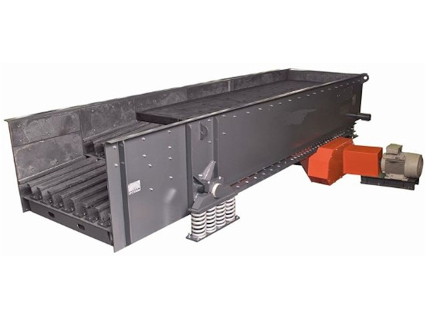
HSV feeder

What Is an Electromagnetic Vibrating Feeder?

An electromagnetic vibrating feeder uses electromagnetic force to generate vibration. The system typically includes an electromagnet, armature, and control unit. The feeder vibrates at high frequency with small amplitude, allowing precise control of material flow.

Operators can adjust the feed rate instantly by modifying the electrical input, which makes this system highly responsive and suitable for automated production environments.

What Is an Electromechanical Vibrating Feeder?

An electromechanical vibrating feeder relies on vibration motors (or unbalanced motors) to generate mechanical oscillation. These motors create centrifugal force that drives the feeder tray.

This design produces larger amplitudes and stronger conveying force, which makes it ideal for handling heavy loads and coarse materials in harsh industrial environments.

Key Differences That Impact Performance

1. Feeding Accuracy and Control

Electromagnetic feeders excel in precision. They allow operators to fine-tune the feed rate almost instantly, which makes them highly suitable for processes that require consistent and controlled material dosing.

Electromechanical feeders, on the other hand, provide stable but less precise control. Their adjustment typically involves changing motor speed, angle, or weight configuration, which is less responsive.

Conclusion:

If your process requires high accuracy (e.g., batching, packaging, or dosing), electromagnetic feeders offer a clear advantage.

2. Material Handling Capacity

Electromechanical vibrating feeders outperform electromagnetic models when it comes to heavy-duty applications. They can handle large particle sizes, high throughput, and abrasive materials without compromising performance.

Electromagnetic feeders are better suited for light to medium loads and fine materials.

Conclusion:

For mining, quarrying, or bulk material transport, electromechanical feeders are the more robust choice.

3. Energy Efficiency

Electromagnetic feeders consume less power because they operate with controlled electromagnetic pulses. They also stop instantly when power is cut, reducing unnecessary energy usage.

Electromechanical feeders require continuous motor operation, which results in higher energy consumption over time.

Conclusion:

If energy efficiency and operating cost reduction are priorities, electromagnetic feeders are generally more economical.

4. Maintenance Requirements

Electromagnetic feeders have fewer moving parts, which reduces mechanical wear. However, they rely heavily on electrical components, which require stable voltage and proper control systems.

For detailed information on the differences between electromagnetic vibrating feeders and electromechanical vibrating feeders, please click to visit: https://www.hsd-industry.com/news/difference-between-electromagnetic-and-electric-vibrating-feeders/

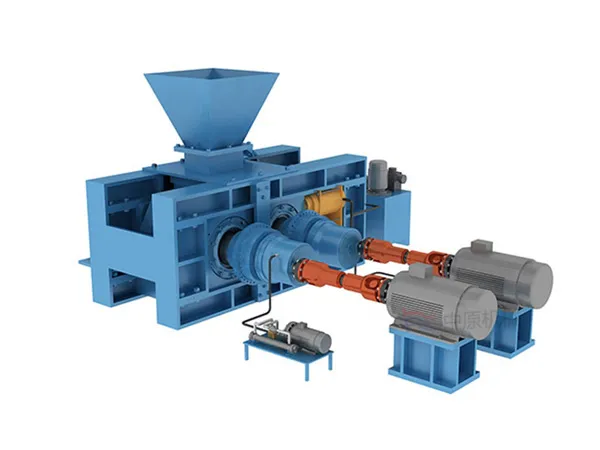
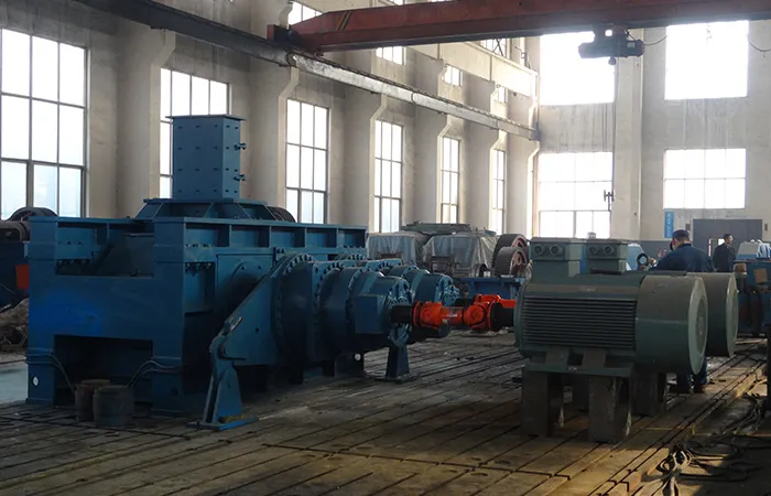
High-Pressure Grinding Rolls (HPGR) have become a cornerstone in modern mineral processing, offering higher energy efficiency, improved particle size distribution, and enhanced downstream processing performance compared to traditional grinding methods. Despite these advantages, HPGR units are not immune to operational challenges. Among the most common and critical issues that operators face are skewing and excessive vibration. If left unresolved, these problems can significantly impact production efficiency, increase maintenance costs, and shorten equipment lifespan.

Understanding the root causes of HPGR skewing and vibration is essential for plant engineers, maintenance teams, and operators seeking to maintain optimal performance. In this guide, we provide a detailed analysis of these issues, their consequences, and practical troubleshooting strategies.

Understanding HPGR Skewing

High-Pressure Grinding Rolls

Skewing occurs when the rolls of an HPGR unit become misaligned relative to each other during operation. This misalignment can result from uneven wear, improper installation, or operational factors such as uneven feed material. When skewing happens, the load distribution between the rolls becomes unbalanced, leading to several undesirable outcomes:

Uneven particle size distribution – Skewing causes inconsistent compression of the ore, which can reduce downstream efficiency in flotation, leaching, or milling operations.

Localized wear – Misalignment concentrates pressure on specific areas of the rolls, accelerating wear on the grinding surfaces and liners.

Energy inefficiency – The motor and drive system may consume more energy to compensate for the uneven load.

Increased maintenance frequency – Continuous skewing accelerates component degradation, resulting in more frequent downtime and repair costs.

Common Causes of HPGR Skewing

Several factors contribute to skewing, and understanding them is the first step in effective troubleshooting:

Incorrect roll alignment during installation – Even minor deviations during setup can trigger skewing once the unit is under load.

Wear and tear of bearings and hydraulic systems – Uneven wear in bearing housings or failure in hydraulic roll alignment mechanisms can shift roll positions.

Uneven feed distribution – HPGR performance depends on a consistent feed layer; oversized or poorly distributed material can cause one roll to experience higher stress.

For more detailed information on troubleshooting high-pressure roller mill tilting and vibration issues, please click to visit: https://www.zymining.com/en/a/news/troubleshooting-hpgr-skewing-and-vibration-issues.html

In the mining and aggregate processing industry, vibrating screens play a vital role in material classification, separation, and dewatering. The stability and efficiency of these machines directly impact overall production capacity and operating costs. Among all core components, the exciter stands out as the driving force behind consistent and reliable performance.

For companies committed to improving production efficiency and reducing downtime and maintenance costs, understanding high-performance mining vibrating screen vibrators is essential. This article provides a comprehensive overview of vibrator structure, advantages, selection criteria, and maintenance strategies to help users make informed decisions based on their actual operational needs.

What Is a Vibrating Screen Exciter?

Cooperation Customer

A vibrating screen exciter is a mechanical device that converts the rotational motion of a motor into a controlled vibratory force. It typically uses eccentric shafts or counterweights to generate consistent vibration, which drives the screen box to move in a defined motion pattern.

In mining environments, exciters must operate under harsh conditions, including heavy loads, continuous operation, and high levels of dust and moisture. Therefore, their design, material quality, and manufacturing precision are critical to ensuring long-term reliability.

Key Features of High Performance Exciters

High performance exciters are engineered to overcome the limitations of conventional designs. They offer several technical advantages that significantly improve equipment performance:

1. Robust Structural Design

Manufacturers design high performance exciters with integrated housings made from high-strength alloy steel. Engineers optimize stress distribution using advanced simulation tools, which enhances fatigue resistance and reduces the risk of structural failure.

This robust design ensures that the exciter maintains integrity even under prolonged heavy-duty operation.

2. Precision Machining and Dynamic Balancing

High-precision machining ensures accurate alignment of eccentric components and bearing seats. Additionally, strict dynamic balancing minimizes unwanted vibration and mechanical deviation.

As a result, the equipment runs more smoothly, with lower noise levels and improved operational stability.

3. Advanced Bearing Systems

High performance exciters typically use heavy-duty roller bearings specifically designed for vibrating applications. These bearings can handle high loads and impact forces while maintaining durability.

A well-designed lubrication system further reduces friction and heat generation, extending bearing life and improving overall reliability.

4. Adjustable Amplitude Function

Many high performance exciters allow operators to adjust vibration amplitude by changing the angle of the eccentric weights. This flexibility enables users to adapt the screening process to different material types and particle sizes.

This feature is especially valuable for operations that handle multiple types of materials.

Benefits in Mining Vibrating Screen Applications

High Frequency Dehydration Vibrating Screen

1. Improved Screening Efficiency

Stable vibration frequency and amplitude ensure uniform material movement across the screen surface. This leads to more accurate particle separation and higher product quality.

For more detailed information about high-performance mining vibrating screen exciters, please click to visit: https://www.hsd-industry.com/news/high-performance-exciters-for-mining-vibrating-screens/

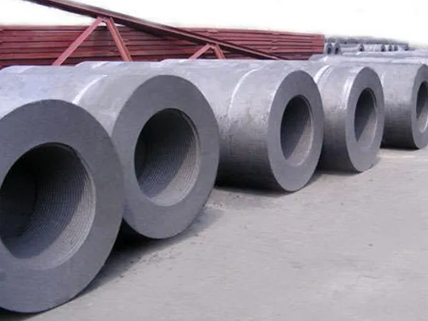
Graphite electrodes play a critical role in electric arc furnaces (EAF) and ladle furnaces, where they are subjected to extreme temperatures often exceeding 3000°C. These electrodes are preferred for their high conductivity, thermal stability, and mechanical strength. However, despite their inherent advantages, graphite electrodes are highly susceptible to oxidation when exposed to high temperatures in the presence of oxygen. Oxidation not only reduces the electrode’s lifespan but also increases operational costs and compromises furnace efficiency. Understanding how to prevent oxidation in graphite electrodes at high temperatures is therefore essential for industries relying on electric arc processes.

Understanding the Oxidation Mechanism in Graphite Electrodes

Graphite oxidation occurs when carbon atoms in the electrode react with oxygen to form carbon monoxide (CO) or carbon dioxide (CO₂). This chemical reaction accelerates at high temperatures and is further exacerbated by the presence of moisture or impurities in the furnace environment. The reaction can be summarized as follows:

C + O₂ → CO₂

2C + O₂ → 2CO

As oxidation progresses, the electrode loses structural integrity, resulting in increased electrical resistance, reduced thermal conductivity, and surface erosion. Ultimately, this leads to frequent electrode replacements and increased downtime, which can significantly impact production efficiency and operational costs.

Effective Strategies to Prevent Oxidation

Preventing oxidation in graphite electrodes requires a combination of material improvements, operational practices, and protective measures. Below are the most effective strategies that can be implemented:

1.Use High-Density, Impurity-Free Graphite Electrodes

The quality of graphite electrodes is the first line of defense against oxidation. Electrodes with high density and low porosity reduce oxygen penetration into the carbon matrix. Additionally, selecting electrodes with minimal impurities, such as metallic residues, reduces the catalytic sites for oxidation reactions. Manufacturers should prioritize electrodes produced from premium petroleum coke and needle coke with uniform particle sizes, as these materials exhibit superior thermal stability.

2.Apply Protective Coatings

Graphite electrodes can be coated with anti-oxidation agents such as pitch or silicon carbide layers. These coatings form a barrier on the electrode surface, reducing direct exposure to oxygen. Regularly inspecting and reapplying these coatings ensures consistent protection. In some advanced applications, ceramic-based coatings have been shown to offer longer-lasting resistance to high-temperature oxidation.

3.Optimize Furnace Atmosphere

Controlling the furnace atmosphere is crucial in minimizing graphite oxidation. Reducing the oxygen concentration in the furnace through inert gas purging or maintaining a slightly reducing environment can slow down the oxidation rate. Operators should also ensure that moisture content is minimized, as water vapor can accelerate carbon oxidation at elevated temperatures.

4.Implement Controlled Electrode Handling

Improper handling of graphite electrodes can create surface cracks, exposing fresh carbon to oxygen and accelerating oxidation. Training personnel to handle electrodes carefully during storage, transport, and installation can significantly reduce mechanical damage. Additionally, storing electrodes in dry, temperature-controlled conditions prevents premature oxidation before use.

5.Monitor Electrode Temperature and Current Load

Graphite electrodes are most vulnerable to oxidation at the tip, where temperatures and electrical loads are highest. Ensuring the furnace operates within recommended voltage and current limits helps maintain uniform electrode temperature and reduces localized overheating. Advanced monitoring systems can track electrode wear and temperature distribution, allowing timely adjustments to prevent excessive oxidation.

6.Regular Maintenance and Inspection

Frequent inspection of graphite electrodes can detect early signs of oxidation, such as surface pitting or darkening. Removing oxidized sections and applying protective coatings can extend electrode life. Additionally, maintaining furnace integrity, including seals and insulation, ensures that oxygen intrusion is minimized.

For more detailed information on the how to prevent oxidation in graphite electrodes at high temperatures, please click to visit:https://www.czgraphite.com/a/news/how-to-prevent-oxidation-in-graphite-electrodes-at-high-temperatures.html

Thin section bearings are widely used in industries that demand compact structures, lightweight components, and high accuracy—such as robotics, aerospace systems, semiconductor equipment, medical devices, and automated machinery. Their unique geometry makes them ideal for designs with limited space, but this same advantage also introduces stricter requirements for installation, operating conditions, and maintenance.

When a thin section bearing fails, the consequences can be far more serious than with conventional bearings: equipment downtime increases, precision is compromised, and repair costs escalate. Understanding why these failures occur and how to prevent them is therefore essential for engineers and machine operators.

Typical Failure Causes of Thin Section Bearings

Thin section bearings

1. Misalignment Under Tight Installation Conditions

Thin section bearings are far less tolerant of misalignment because of their narrow cross-section.

Even a minor angular or parallel shift can cause uneven stress distribution.

Rolling elements begin to contact the raceways in a concentrated area rather than distributing the load evenly.

Over time, this leads to accelerated wear, vibration, and eventual spalling.

In robotic joints or precision platforms, even fractional misalignments can shorten bearing life dramatically.

2. Contamination in Compact Operating Environments

Thin section bearings often work inside assemblies where space is extremely limited. This increases the chance that:

Dust, machining debris, metal chips, or moisture enter the bearing cavity.

Contaminants scratch the raceway surface and create micro-pitting.

Lubricant deteriorates faster, turning abrasive and causing rolling-element fatigue.

In cleanroom or medical applications, contamination is one of the most common root causes of failure.

3. Load Beyond the Rated Capacity

Thin section bearings are carefully engineered for specific radial, axial, and moment loads. When these limits are exceeded:

Brinelling marks—small permanent indentations on raceways—may appear.

In heavy-duty cases, the bearing may crack or deform.

Moment load miscalculations are particularly common in rotary tables and robotic arms.

For more detailed information on failure analysis and solutions for thin-section bearings, please click to visit: https://www.lynicebearings.com/a/blog/thin-section-bearing-failure-analysis-and-solutions.html

The vibrating screen exciter is the core of any screening system. It generates the vibration force needed to move materials across the screen surface, directly affecting efficiency, throughput, and machine lifespan. A high-quality exciter ensures stable performance, reduced maintenance costs, and improved product quality.

This guide covers key components, structural design considerations, and optimization strategies to help engineers, plant managers, and buyers make informed decisions.

What Is a Vibrating Screen Exciter?

A vibrating screen exciter (also called an exciter unit) is a mechanical device that converts rotational energy into oscillations required for effective material screening. It is widely used in:

Mining and mineral processing

Aggregates and construction materials

Coal preparation

Metallurgy

Chemical and recycling industries

A well-designed exciter ensures stable vibration amplitude, balanced force output, and consistent screening efficiency.

DVE4.1S

Key Components of a Vibrating Screen Exciter

Understanding core components is essential for selection, operation, and maintenance:

1. Housing / Exciter Body

Supports bearings, shafts, and gears

Made from high-strength steel or cast alloy

Precision machining ensures stable vibration

2. Shaft(s)

Single or dual shaft depending on design

Transmits rotational force

Heat-treated to withstand heavy cyclic loads

3. Bearings

Heavy-duty spherical or cylindrical roller bearings

Designed for high-speed rotation and vibration stress

Bearing quality directly impacts exciter lifespan

4. Gears

Synchronize shaft motion

Ensure accurate vibration amplitude and direction

5. Lubrication System

Oil or grease-based depending on design

Prevents premature wear and overheating

Critical for long-term reliability

Structural Design Factors Affecting Exciter Performance

Several structural elements influence exciter performance. Optimizing these ensures higher efficiency, lower downtime, and longer equipment life.

For more detailed information on the structural design of vibration screen exciter guidelines, please click to visit: https://www.hsd-industry.com/news/vibrating-screen-exciter-structure-design/

Slewing bearings are core rotating components in construction machinery, lifting equipment, wind turbine generators, and large machine tools, and their performance directly affects equipment safety and production efficiency. However, tooth breakage is a frequent problem after long-term use, leading not only to equipment downtime but also potentially high maintenance costs. So, why do slewing bearings break teeth? And how can this be prevented scientifically? This article will provide a systematic analysis.

Main Causes of Slewing Bearing Tooth Breakage

Slewing bearings

1. Overload Operation

Slewing bearings are designed with a rated load range. Overloading causes stress concentration on the tooth surface, accelerating material fatigue and ultimately leading to tooth breakage. This is especially true in cranes or large excavators, where improper operation poses a very high risk of overloading.

2. Improper Lubrication

Insufficient lubrication or low-quality lubricating oil leads to direct metal-to-metal contact between the tooth surfaces, increased friction, localized temperature increases, and rapid gear wear. Neglecting lubrication maintenance over a long period is a major cause of tooth breakage.

3. Installation and Adjustment Issues

The installation accuracy of the slewing bearing directly affects the gear meshing state. Uneven installation or preload can lead to uneven gear stress and excessive localized stress, easily causing tooth surface damage or even tooth breakage.

4. Material and Heat Treatment Defects

Inadequate strength, hardness, and surface treatment of gear steel can easily cause micro-cracks under high stress environments, eventually leading to tooth breakage due to long-term accumulation. Uneven carburizing or insufficient quenching are also common hidden dangers.

5. Harsh Operating Environment

High temperatures, dust, and corrosive media can accelerate tooth surface wear or corrosion, reduce load-bearing capacity, and increase the risk of tooth breakage.

Scientific Prevention Measures for Slewing Bearing Tooth Breakage

Slewing bearings

1. Strict Load Control

Ensure equipment operates within its design load range and avoid frequent overloading. For high-load machinery, slewing bearings with higher rated loads can be selected to increase safety margins.

2. Optimize Lubrication Scheme

Use lubricating grease that meets specifications and regularly check the oil level and quality to ensure adequate lubrication of the tooth surface. For heavy-duty or high-speed operating equipment, consider a circulating lubrication system to improve tooth surface protection.

For more detailed information on the causes and prevention of slewing bearing tooth fracture, please click to visit: https://www.mcslewingbearings.com/a/news/causes-and-preventive-measures-for-broken-teeth-in-slewing-bearings.html

In industrial machinery, lifting equipment, and automation systems, slewing bearings, as core components for load bearing and rotation, directly affect the operational stability and lifespan of the equipment. Besides materials, design, and lubrication methods, the surface roughness of the bearing is also a crucial factor determining its performance. This article will delve into the multifaceted impact of surface roughness on slewing bearings and provide optimization suggestions to help companies improve equipment reliability and efficiency.

What is Bearing Surface Roughness?

Bearing surface roughness refers to the degree of microscopic unevenness on the bearing raceway surface, usually expressed by parameters such as Ra and Rz. Excessive or insufficient surface roughness will have varying degrees of impact on bearing operation; therefore, properly controlling surface roughness is a crucial aspect of bearing manufacturing and application.

Main Impacts of Surface Roughness on Slewing Bearings

1. Impact on Friction and Energy Consumption

Excessively high bearing surface roughness leads to increased friction between the rolling elements and the raceway, thereby increasing the equipment’s energy consumption and heat generation. This not only reduces bearing efficiency but may also accelerate lubricant aging, shortening bearing life.

Conversely, an overly smooth surface may cause rolling element slippage, reducing rolling friction efficiency. Therefore, maintaining appropriate surface roughness helps achieve low friction and high efficiency operation.

2. Impact on Wear and Fatigue Life

Under high load and frequent start-stop conditions, minute defects on the raceway surface of slewing bearings can easily form stress concentration points, accelerating wear and even leading to early fatigue cracks. Appropriate surface roughness can improve lubricant film formation, reduce direct metal-to-metal contact, and thus extend bearing life.

For more detailed information on the impact of surface roughness on slewing bearing performance, please click to visit: https://www.lynicebearings.com/a/blog/effects-of-surface-roughness-on-slewing-bearing-performance.html